
Electronic Door Lock Security Key

The electronic door lock security key system utilizes a combination of components designed to enhance security and convenience. The circuit typically includes a microcontroller, which processes the input from a keypad or a set of buttons. Upon entering the correct key sequence, the microcontroller generates an output signal.
This output signal can be used to activate a relay, which serves as an electronic switch. When the relay is energized, it allows current to flow to the door lock mechanism, effectively unlocking the door. The relay is chosen based on the voltage and current requirements of the locking mechanism, ensuring compatibility and reliability.
Additional components may include diodes for flyback protection across the relay coils, resistors to limit current to the microcontroller inputs, and capacitors for noise filtering. A power supply circuit is also essential, providing the necessary voltage levels for the microcontroller and the relay.
For enhanced security, the system may incorporate features such as a timeout function, which automatically locks the door after a set period or an alarm system that triggers if an incorrect key sequence is entered multiple times. The entire setup can be housed in a secure enclosure to prevent tampering.
In summary, the electronic door lock system is a sophisticated solution that combines modern electronic components to provide a reliable and secure method for accessing locked doors.This is the circuit diagram electronic door lock security key system. It means that this security system circuit is the combination of pressed key itself (not the mechanical), the output can be connected to drive the relay to open the door.. 🔗 External reference
Related Circuits
The operation of a 303MHz circuit has been covered in our project WIRELESS DOORBELL. We are not going over how the circuit works but explain the importance of some of the components and how they affect the range. The...
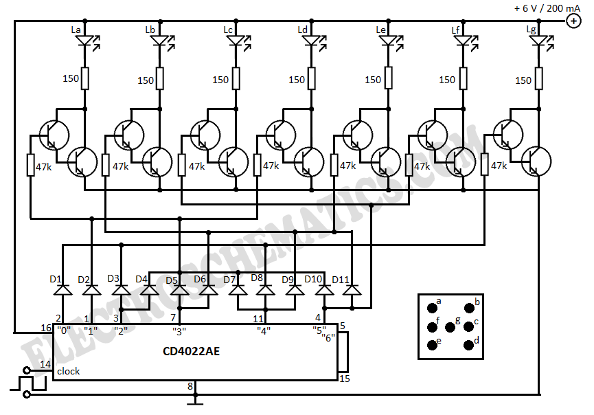
This electronic dice displays results using LEDs arranged to represent each face of a die. The circuit diagram incorporates IC 4022, which functions as a counter. The electronic dice circuit utilizes a combination of integrated circuits and discrete components to...
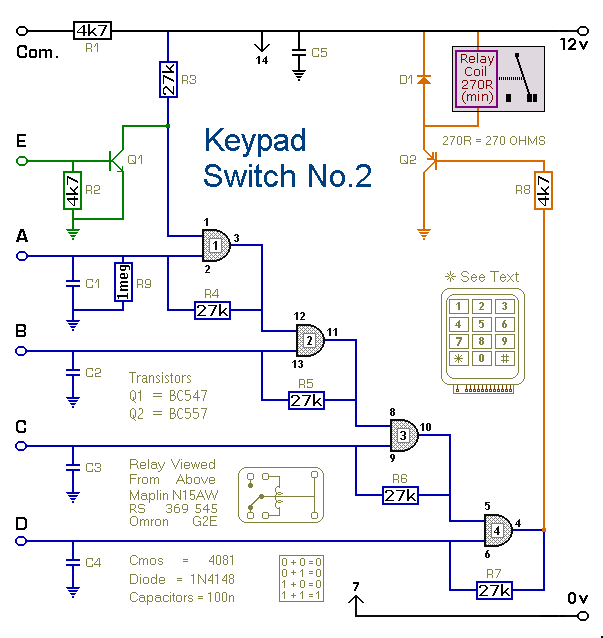
This is a simplified version of the 4-Digit Keypad Controlled Switch. The design has been modified to reduce the complexity of the circuit and the number of components required. Consequently, the code may be somewhat less secure; however, it...
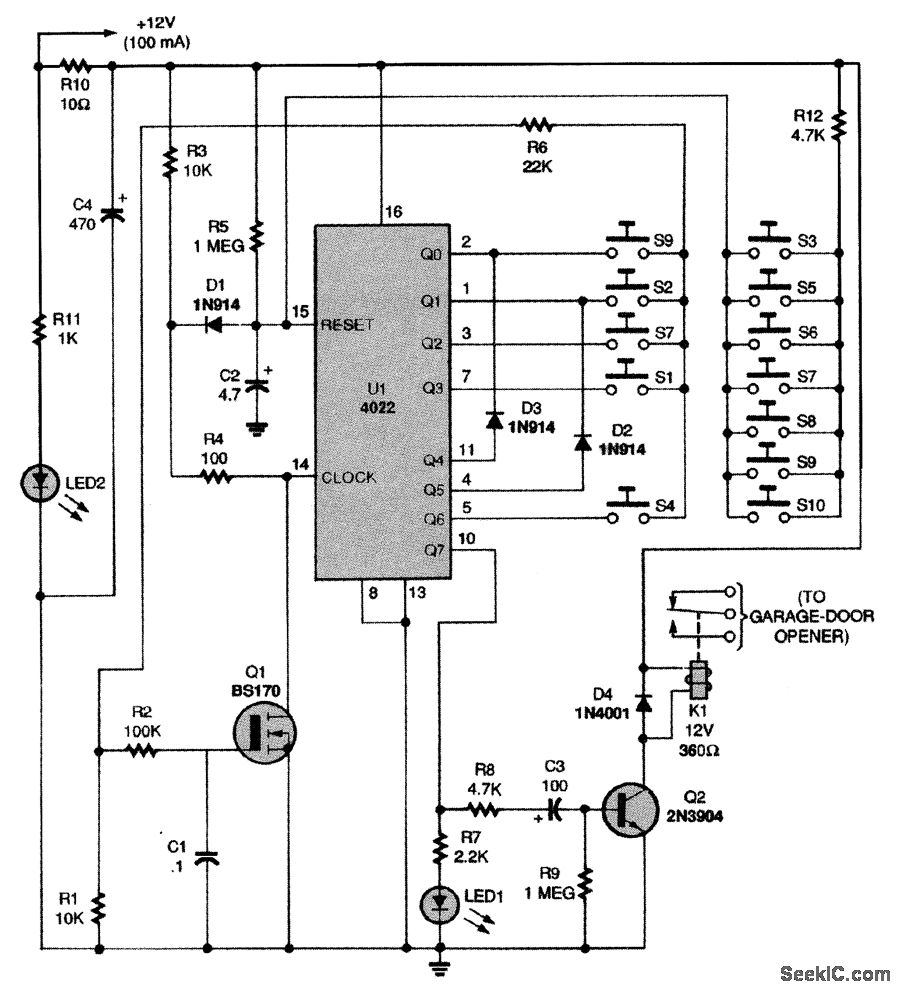
This circuit relies on the input of a correct sequence code. An incorrect number that is not part of the code triggers a reset of the circuit. When the correct code is entered, Q2 activates relay K1 for a...
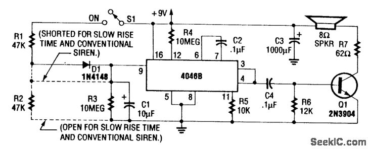
For a normal wailing tone, short D1 and leave R2 open. To achieve a fast rise and slow fall in frequency, include both D1 and R2. Utilizing a CD4046B with a diode-RC network as illustrated generates a siren tone...
Craftsman Garage Door Opener Schematic and Installation Manuals. Sears Craftsman Garage Door Opener Parts. With 15 years in the business, Garage Door Openers Superstore is a leading provider. The schematic for the Craftsman Garage Door Opener provides a comprehensive overview...