
electronic door release

The circuit comprises a microcontroller that processes the input from a keypad where the user enters the four-digit code. The microcontroller is programmed to recognize the specific sequence of digits. Upon successful entry of the correct code, the microcontroller sends a signal to a relay driver circuit, which then activates the relay. The relay serves as a switch that can handle higher voltage and current loads, allowing it to control the door-release mechanism effectively.
The system should include a power supply circuit that can either be connected to mains power or utilize a battery for operation. If a battery is used, a low-power microcontroller is recommended to ensure long battery life. The circuit may also incorporate a voltage regulator to maintain stable operation despite variations in power supply.
Additional features may include an LED indicator to provide visual feedback when the relay is energized and a buzzer that sounds upon successful code entry or incorrect attempts. For security purposes, the system can be designed to limit the number of incorrect entries before locking out further attempts for a specified duration.
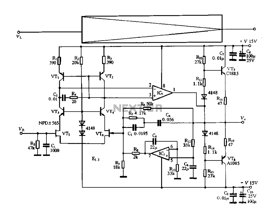
In terms of layout, the circuit should be designed to minimize the distance between the microcontroller, keypad, and relay to reduce the risk of interference and ensure reliable operation. Proper decoupling capacitors should be placed near the power pins of the microcontroller to filter out noise. The relay contacts should be rated appropriately for the load they will control, and the use of flyback diodes across the relay coils is essential to protect the microcontroller from voltage spikes when the relay is de-energized.This circuit is designed to operate an electrical door-release mechanism - but it will have other applications. When you enter the four-digit code of your choice - the relay will energize for a preset time period.
Use the relay contacts to power the release mechanism. The standby current is virtually zero - so battery power is a realistic option.. 🔗 External reference
Related Circuits
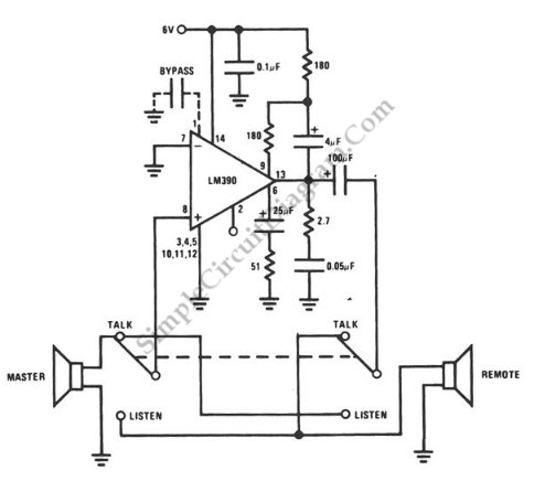
This intercom circuit is suitable for use with a doorbell. It utilizes the speakers as both microphones and loudspeakers. This intercom is designed to facilitate communication. The intercom circuit described operates by utilizing a dual-function speaker system, where the same...
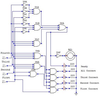
The circuit functions as a random number generator, producing numbers from 1 to 6. It features a line of LEDs, each corresponding to a number in the range of 1 to 6. When the push button S1 is pressed...
This document presents a collection of engaging and challenging electronic circuits that can be built for enjoyment. The author has a long-standing passion for electronics, having studied the subject since middle school and developed numerous circuits over the years....
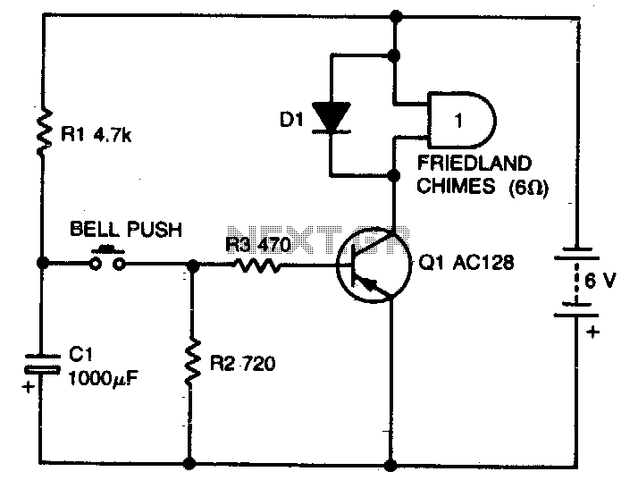
With the specified values, this simple circuit will allow one operation approximately every 10 seconds. Capacitor C1 charges through resistor R1 when the button is released. Increasing the resistance of R1 will lengthen the delay. This circuit functions as a...
The electronic switch functions as a multifunctional preamplifier. It features a five-way touch electronic switch, a high-speed DC servo RIAA ultralow distortion amplifier, and can control volume, tone, and power amplifier electrical path phase. The TC9152, shown in Figure...
This guitar amplifier electronic architecture utilizes a robust conventional circuit design for the power amplifier, employing a single-rail supply of approximately 60V and capacitor coupling for the speakers. The advantages of this configuration for a guitar amplifier include a...