
Electronic LED compass

The compass circuit utilizes the AT90S2313 microcontroller, which is an 8-bit AVR microcontroller with a rich set of features suitable for this application. The circuit is designed to interpret directional data and visually represent it through a series of eight Light Emitting Diodes (LEDs). Each LED corresponds to a specific cardinal or intercardinal direction, providing a clear visual indication of orientation.
The microcontroller is programmed to read input from a suitable sensor, such as a magnetometer or a digital compass module. This sensor outputs directional information, which the AT90S2313 processes to determine the current heading. The microcontroller then activates the appropriate LEDs based on the calculated direction.
The circuit may include a voltage regulator to ensure stable operation of the microcontroller and LEDs, as well as resistors to limit the current flowing through each LED, preventing damage. The design should also consider the use of decoupling capacitors near the power supply pins of the microcontroller to filter out noise and ensure reliable operation.
In addition to the basic functionality, the circuit can be enhanced with features such as adjustable sensitivity, calibration routines for the sensor, and a user interface for configuration. This can be implemented using additional buttons or a small display to provide feedback to the user.
Overall, this compass circuit is a practical application of microcontroller technology, providing a straightforward yet effective way to visualize directional information using LEDs.This is a compass circuit based at AT90S2313. The output drives 8 LEDs to indicate the different horizon directions. 🔗 External reference
Related Circuits

This chip from Texas Instruments is easy to integrate into designs and is suitable for the assembly of lighting devices. A consistent quality and expected performance can be easily achieved. The complete circuit consists of a control integrated circuit...
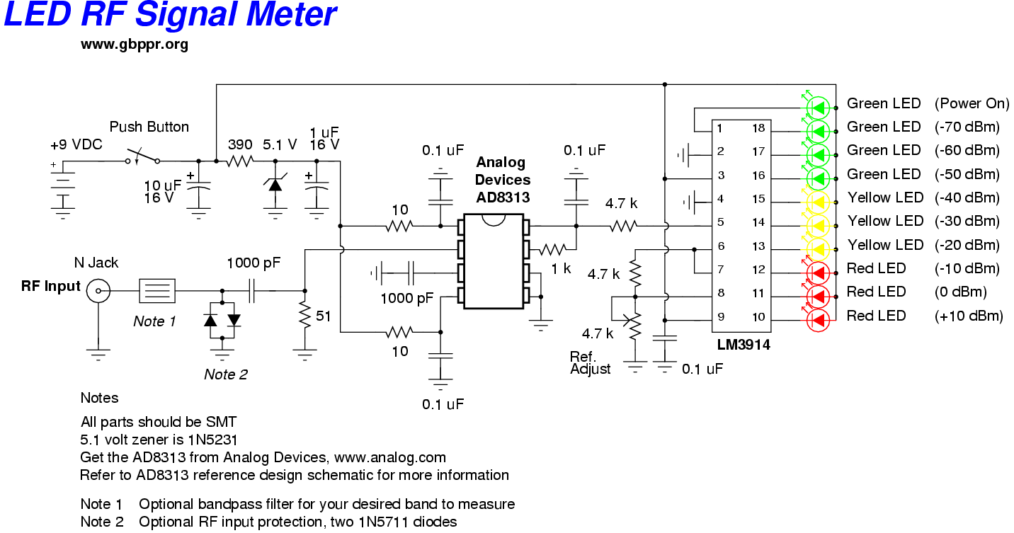
This RF Wave Absorption meter detects signals from 10 centimeters to 10 meters, depending on the setting of the 22 MegOhm gain adjustment potentiometer and the transmitter power. The RF signal is captured through germanium OA91 diodes and rectified...

This circuit is a modified Hartley oscillator that incorporates additional components. It utilizes a small audio transformer, specifically the LT700 model. The primary winding is center-tapped with an impedance of 1 kΩ at 1 kHz, while the secondary winding...

This application note discusses the use of SEPIC power modules to supply the necessary power for driving high-brightness LED arrays. These arrays serve as display backlights and necessitate a wide dimming range. The SEPIC configuration offers an efficient and...

The LED guard-rail tube, also known as the decorative tube, is an advanced LED illumination product designed for decorative purposes. It utilizes red, green, and blue LEDs as light sources, employing microelectronics and digital technology to create color chasing...
The electronic counter of the winding machine utilizes an LED digital display to indicate the number of turns of the wound coil, with a maximum counting capacity of 9900 turns. The operational principle of the winding machine circuit consists...