
Electronic lock using the 4022 octal counter

The described electronic lock system utilizes a 40022 octal counter as its core component, which functions to manage the input sequence for unlocking. Upon powering the system, capacitor C2 is initially charged through resistor R5, ensuring that the reset input of the counter remains high. This configuration results in output Q being activated while all other outputs remain low, establishing the initial state of the lock.
The input mechanism includes a set of switches, with S4 designated as the primary switch for initiating the unlocking sequence. When S4 is engaged, it triggers the BS170 MOSFET, which is part of a debouncing network formed by resistor R2 and capacitor C1. This action sends a clock pulse to the 4022 octal counter, facilitating its operation. Concurrently, capacitor C2 discharges through resistor R4 and diode D1, effectively removing the reset signal from the counter and allowing it to increment its count.
The timing for the charging of C2 through R5 is critical; it determines the maximum allowable interval before the next key press is registered. This design ensures that the system is responsive to user input, requiring a specific sequence of key presses to achieve unlocking.
Once the correct sequence of keys has been entered within the designated time frame, output Q7 is activated for a duration of approximately four seconds. This output is connected to an unlocking relay, which physically disengages the lock mechanism. The system is designed to allow for reprogramming of the unlock code by altering the configuration of the switches. The default sequence provided is 4-8-0-1-5-7-0.
Furthermore, the design permits the substitution of the 4022 octal counter with a 4017 decade counter. This modification enables the inclusion of two additional digits in the combination code, enhancing the security and flexibility of the locking mechanism. The overall architecture of the circuit is conducive to both robustness and user adaptability, making it suitable for various applications requiring secure access control.The heart of the lock is the 40022 octal counter. When first powered C2 is charged via R5 so the reset input of the counter is kept high. That causes output Q to go high while all the other outputs are low. With the switches wired as shown, when S4 is pressed, the BS170 mosfet is switched on via debouncing network R2/C1, and the 4022 recieves a clock pulse. Also C2 is discharged via R4 and D1, removing the reset signal of the counter, allowing it to advance.
The time required for C2 to charge via R5 is the maximum time that can lapse before the next key is pressed in time. When all keys have been pressed in time and in the correct order, Q7 goes high for about four seconds to drive the unlocking relay etc. You can change the code by reviewing the switches. The code for the lock shown in image is 4-8-0-1-5-7-0. However, the 4022 octal counter can be replaced by a 4017 divide by 10 counter that will make it possible to add two more digits to the combination code.
🔗 External reference
Related Circuits
The circuit below is similar to the one above but can be used with a laser pointer to toggle the relay rather than a push button. The IR photo transistor Q1 (Radio Shack 276-145A) or similar is connected to...
This circuit measures the distance covered during a walk. The hardware is housed in a compact box that can be conveniently placed in a pants pocket. The display is designed as follows: the leftmost display, D2 (the most significant...
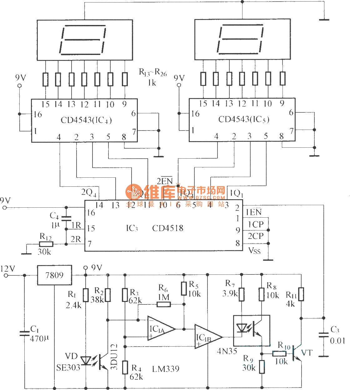
The circuit includes an optical input circuit (VD, 3DU12), a pulse forming circuit (IC1A, IC1B functioning as a voltage comparator; optical coupler; transistor switching circuit), and a counting and display circuit. The circuit architecture consists of several key components that...

This series-feedback configuration of components provides a high input impedance and stable, wide-band gain video amplifier suitable for general-purpose applications. Below is the schematic representation of the circuit. The described video amplifier circuit employs a series-feedback topology, which is instrumental...
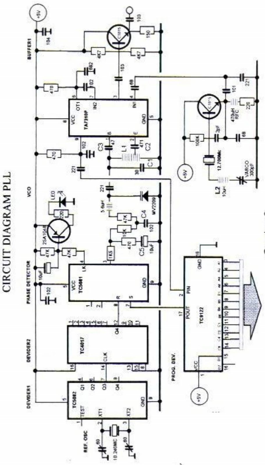
The primary function of the phase-locked loop (PLL) phase detector is to compare the input phase of the voltage-controlled oscillator (VCO) signal with a reference signal, resulting in a phase difference. This phase difference generates a voltage difference, which...
This project consists of two circuits on two separate boards. The initial circuit is built around a PIC16F628A microcontroller. It was constructed on an experimental PC board utilizing surface-mount components and was completed in under one hour, with an...