
Electronic locust killer device 2

The electronic locust killer device operates by generating a high-frequency square wave signal through the square wave oscillator. The counting divider integrated circuit (IC) is responsible for dividing the frequency of the input signal to produce a square wave output. Resistors R5 and R6 are used to set the timing characteristics of the oscillator, while capacitor C1 helps in shaping the waveform. Potentiometer RP allows for fine-tuning of the frequency, enabling the device to adapt to different environments or target locust populations effectively.
The high-voltage generator circuit is activated by the square wave output from the oscillator. Transistors Q1 and Q2 are arranged in a push-pull configuration to amplify the signal and generate a high-voltage output. Relay K serves as a switch that is triggered by the output from the transistors, enabling the high-voltage circuit to discharge at the appropriate moment to incapacitate locusts. This combination of circuits allows for effective pest control by utilizing electrical discharge to deter or eliminate locust populations in agricultural settings.
Overall, the design of the electronic locust killer device integrates these components to create a reliable and efficient method for managing locust infestations, thereby protecting crops and enhancing agricultural productivity.The electronic locust killer device is composed of the square wave oscillator circuit and high-voltage generator circuit, and the cirucuit is shown in Figure 3-192. Square-wave oscillator is composed of the counting divider lC and resistors R5, R6, capacitor Cl and potentiometer RP.
High-voltage generator is composed of the transistors VI, V2, the relay K, r.. 🔗 External reference
Related Circuits
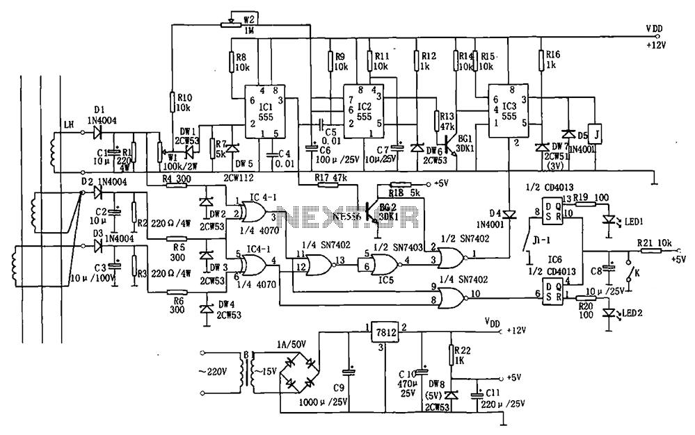
The electrical equipment overload and phase failure protection circuitry includes a +12V and +5V DC power supply, an AC transformer, voltage comparators, timers for blockade, a relay control circuit, and a phase loss protection circuit. The DC power supply...
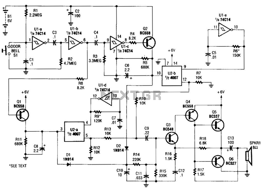
When the doorbell switch is pressed, two monostable stages are sequentially activated, applying bias to a pair of voltage-controlled resistor stages. These stages modulate the outputs from a pair of tone generators. The resulting signals are then fed to...

Freescale Semiconductor has introduced what it claims to be the industry's first tire pressure monitoring system (TPMS) featuring a capacitive pressure sensor designed for ultra-low power consumption and precise sensing. "By utilizing capacitive sensor technology, we achieve low power...
The LED moving font consists of individual modules, each containing 64 LEDs arranged in an 8x8 matrix. These modules can be cascaded to achieve the desired font size. Each module is managed by the LED display driver MAX7219 (or...

This smoke detector electronic project is designed using the LM1801 and common electronic components. The smoke detector circuit diagram does not utilize ionization detection, gas sensors, or optocouplers; instead, it employs two photoresistors (LDRs) and an LED. The circuit...
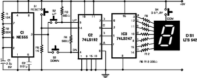
The following circuit illustrates the NE555 Timer used in an electronic scoring game circuit diagram. Features: The circuit consists of a timer integrated circuit (IC), along with various additional components. The NE555 timer is a versatile and widely used integrated...