
NE555 Timer For Electronic Scooring Game

The NE555 timer is a versatile and widely used integrated circuit that can operate in different modes, including monostable and astable configurations. In the context of an electronic scoring game, the NE555 timer can be employed to generate precise timing intervals for scoring events, such as counting points, managing game rounds, or controlling the duration of player turns.
In this circuit, the NE555 timer is typically configured in a monostable mode, where it produces a single output pulse in response to a triggering event. This pulse can be used to activate a score counter or illuminate an LED to indicate a score change. The duration of the output pulse is determined by external resistors and capacitors connected to the timer, allowing for flexibility in timing based on game requirements.
The circuit may also include additional components such as resistors, capacitors, and diodes to ensure stable operation and to filter any noise that may affect the timer's performance. A power supply is necessary to provide the required voltage to the NE555 timer and other components in the circuit.
For user interaction, push-button switches can be integrated into the design, allowing players to register scores manually. The output of the NE555 timer can be connected to a display unit, such as a seven-segment display or an LCD, to visually represent the scores in real-time.
Overall, the NE555 timer circuit for an electronic scoring game is a practical application that showcases the timer's capabilities in a fun and engaging manner, enhancing the gaming experience through accurate score management and timing control.The following circuit shows about NE555 Timer For Electronic Scooring Game Circuit Diagram. Features:The circuit comprises a timer IC, with a .. 🔗 External reference
Related Circuits
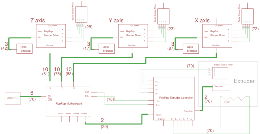
This page outlines the wiring procedure for the RepRap Version II "Mendel." Prior to connecting the machine, it is essential to test the circuit boards individually, as detailed on this page. The overall Mendel wiring diagram is available; clicking...
Here we have three choices, with which we can make electronic switches that use our touch or pressing (push button). We thus exploit the very big resistance of entry, that present the gates CMOS. In the fig.1 we have...
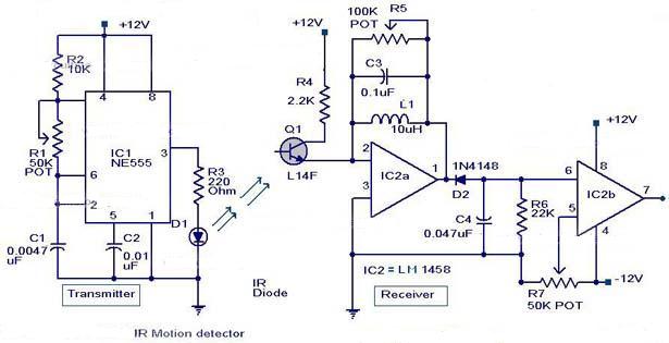
The following circuit illustrates an Infrared Motion Sensor circuit diagram. Features include the use of the NE555 integrated circuit, with a detection zone coverage of 80 degrees. The Infrared Motion Sensor circuit utilizes the NE555 timer IC configured in a...
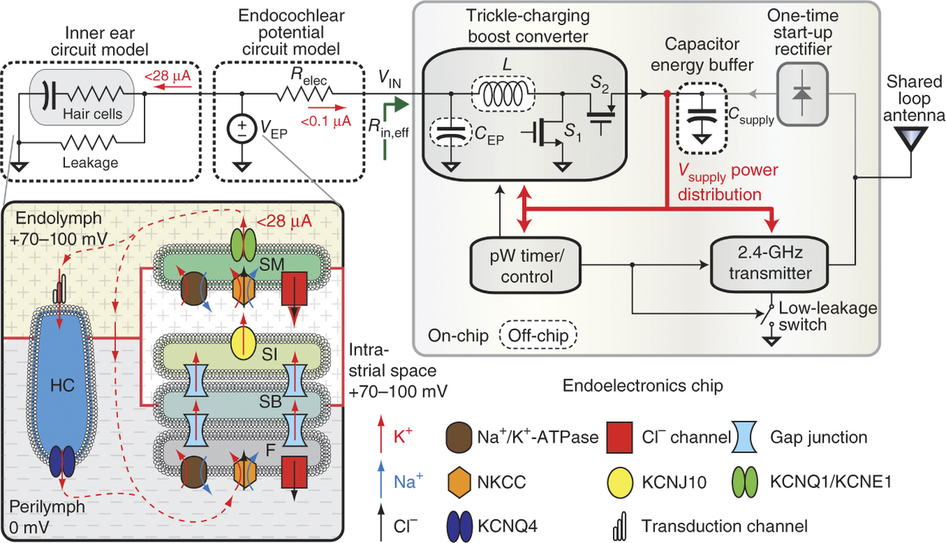
To generate and maintain the endocochlear potential (EP), perilymphatic potassium ions (K+) enter fibrocytes (F) through the Na+/K+-ATPase and Na-K-Cl cotransporter. Gap junction networks connect fibrocytes to strial basal (SB) and intermediate (SI) cells, allowing ions to enter the...
Six timing positions suited to different skin types; timing affected by sunlight intensity. This timer was designed for individuals seeking to achieve a tan. The electronic timer circuit described is intended for use in tanning applications, specifically designed to cater...
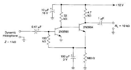
This microphone preamplifier electronic project is based on transistors and is capable of approximately 70 dB or more gain at audio frequencies. The gain of this circuit is roughly equal to the product of the hfe (current gain) of...