
Electronic Muscle Stimulator Circuit

The electronic muscle stimulator circuit operates by delivering electrical impulses through electrodes placed on the skin. These impulses mimic the natural signals sent by the nervous system to stimulate muscle contractions. The circuit typically consists of a microcontroller, which generates the desired pulse patterns, a power supply to provide the necessary voltage, and a driver circuit to amplify the signals before they reach the electrodes.
Key components of the circuit include:
1. **Microcontroller**: This component is programmed to control the timing, frequency, and duration of the electrical impulses. It allows for customization of the stimulation patterns based on user needs.
2. **Power Supply**: A stable power source is essential for the operation of the circuit. This could be a battery or an AC-to-DC converter, depending on the design. The power supply must provide sufficient voltage and current to drive the electrodes effectively.
3. **Driver Circuit**: This section amplifies the signals generated by the microcontroller. It may include transistors or operational amplifiers to ensure that the output signals are strong enough to stimulate the muscles.
4. **Electrodes**: These are placed on the skin and are the interface between the circuit and the body. They can be adhesive pads or other types designed to ensure good contact with the skin for effective stimulation.
5. **Control Interface**: A user-friendly interface, which may include buttons or a touchscreen, allows the user to select different modes of stimulation, adjust intensity levels, and set timers for treatment sessions.
6. **Safety Features**: To ensure safe operation, the circuit may include features such as current limiting, automatic shutoff after a certain period, and isolation between the user and the electrical components.
This electronic muscle stimulator circuit is beneficial for various applications, including physical therapy, rehabilitation, and pain management, providing a non-invasive method to enhance muscle function and alleviate discomfort.This is an electronic muscle stimulator circuit that stimulates nerves of that part of your body where electrodes are attached. It is useful to relieve hea.. 🔗 External reference
Related Circuits

The time IO-bit conversion operates at 3.3 MHz with a clock signal. This converter utilizes a 2504 12-bit register in successive approximation mode, where the conversion signal for the short-cycle end is derived from the first bit utilized in...
A simple USB FM transmitter that can be used to play audio files from an MP3 player or computer on a standard VHF FM radio by connecting it to a USB port. The circuit does not require any coils...
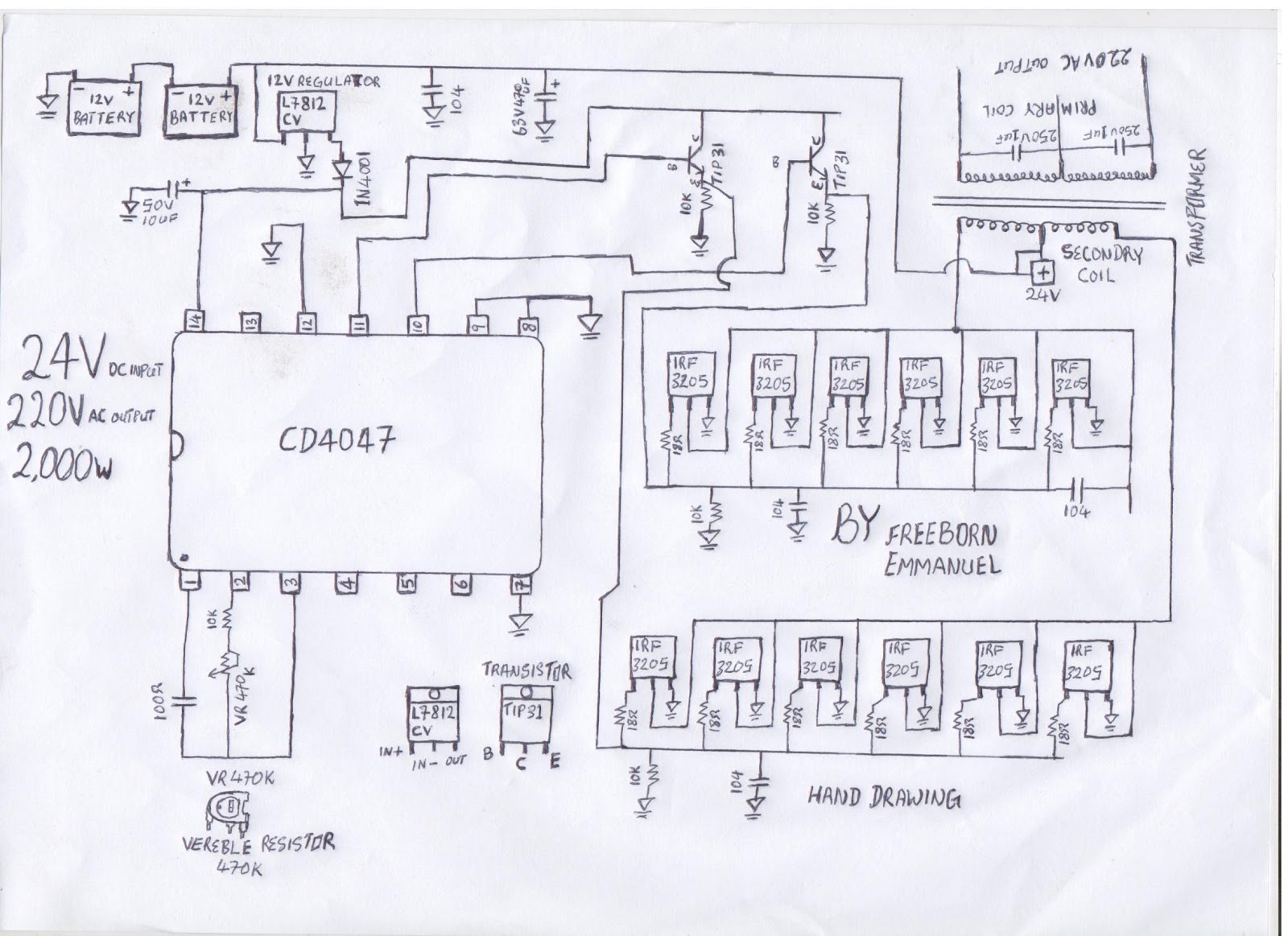
The diagram illustrates a modified square wave inverter circuit. By adjusting the frequency resistor (VR 470k), the inverter's output frequency can be optimized to effectively power a freezer compressor and various other electronic appliances in a living room. The...

This device offers numerous implementation possibilities due to its wide input voltage range and large maximum output current across a broad output voltage spectrum. It features long battery life and low power consumption owing to its high efficiency and...

The Infrared IR Receiver circuit consists of a phototransistor, a microcontroller, and an amplifier. Understanding the data transfer between these three components is essential for successfully operating the circuit. The phototransistor receives digitally encoded data from an IR emitting...
This document does not aim to provide an extensive account of the integrated circuits (ICs) used in this circuit. For additional information on this topic, please refer to the "Flip-Flop Made With A LM556 Timer Chip" section and the...