
Electronic Roulette Game

The circuit utilizes two operational amplifiers, U1A and U1B, configured as oscillators to generate a variable frequency output. The resistor R14 plays a crucial role in determining the initial frequency of oscillation by setting the charge and discharge time constants for capacitor C2. As C2 charges, the voltage across it increases, which in turn affects the feedback loop of the oscillators, leading to a gradual decrease in oscillation frequency.
The LED array, connected through resistor R10, displays the output of the oscillators. The roulette-wheel effect is achieved as the frequency of the oscillation decreases, resulting in a visual representation reminiscent of a spinning wheel. Each LED corresponds to a number, and as the oscillation slows, one specific LED will remain lit, indicating the winning number in the game.
The design can be further enhanced by incorporating a reset mechanism to allow the user to restart the oscillator sequence, as well as adjustable components to fine-tune the speed and duration of the oscillation. Additional features may include a display driver for larger LED arrays or integration with microcontrollers to introduce programmable elements into the game, enhancing user interaction and experience. R14 is set for an initial "starting" speed of the oscillator U1A and U1B. As C2 charges, oscillation begins slowin g down as C2 discharges, giving a roulette-wheel effect on LED SI through 10. The LED that remains on is the winning number.
Related Circuits
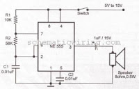
This circuit generates an oscillating frequency of approximately 1 kHz, which can be adjusted by changing the value of resistor R1. The speaker will emit a continuous beep sound at this frequency. The circuit utilizes a basic oscillator configuration,...
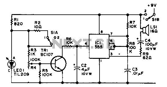
The integrated circuit (IC) operates as an astable multivibrator that is controlled by an external transistor. S1A/B serves as the on-off toggle switch. The astable multivibrator configuration is commonly utilized in various applications, including pulse generation, clock signals, and LED...
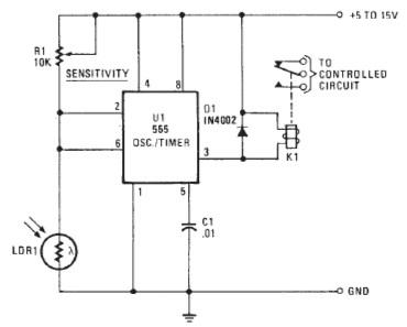
The following circuit illustrates a Photo Alarm Electronic Circuit. This circuit is based on the 555 Timer IC and incorporates features such as an LDR (light-dependent resistor). The Photo Alarm Electronic Circuit utilizes a 555 Timer IC configured in monostable...
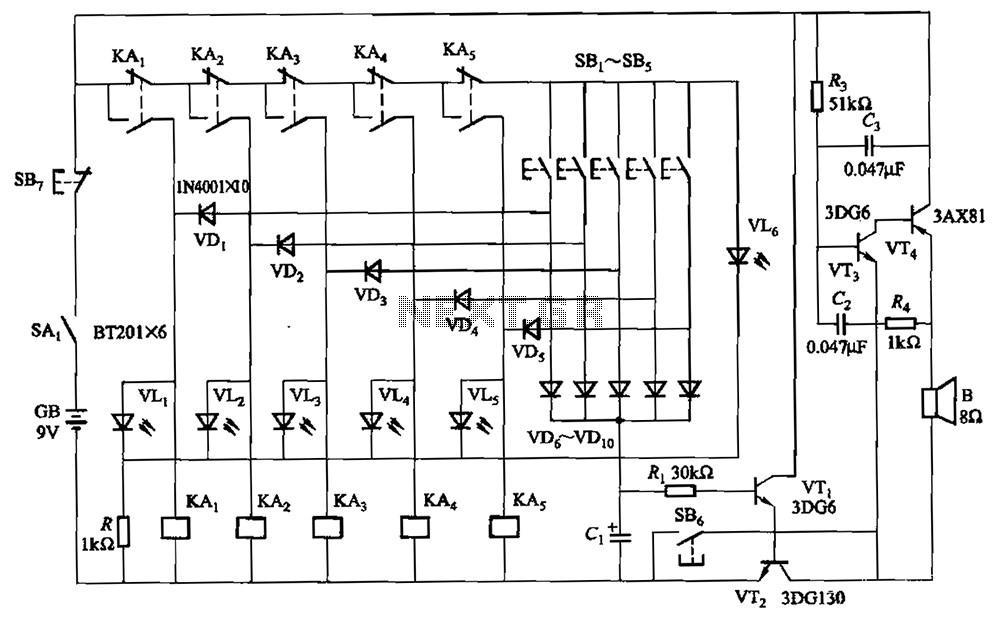
A relay-style circuit designed for a five electronic responder group. This circuit features self-locking capabilities, sound and light displays, time monitoring, and additional functions. The circuit includes a monitoring time button operated by the moderator. When this button is...
The allowable reduction in system performance. For a fire control radar, the acceptable degradation is usually expressed as a reduction in range; for example, the maximum lock-on range might be degraded by 25 percent without loss of essential defense...
This circuit is a modification of the Hartley oscillator, incorporating several additional components. It utilizes a small audio transformer. The modified Hartley oscillator circuit enhances the traditional design by integrating extra components that can improve performance characteristics such as stability,...