
Electronic Slot Machine Circuit

The electronic slot machine circuit comprises a well-structured arrangement of components to facilitate its operation. The heart of the timing mechanism is IC1, a 555 timer configured in astable mode, generating a continuous stream of clock pulses. These pulses are essential for synchronizing the operations of the display driver ICs, specifically IC4, IC5, and IC6. Each of these ICs is responsible for driving one of the three common-cathode 7-segment LED displays, allowing the machine to represent various symbols visually.
The symbols displayed include an L, a 7, and a bar, which are fundamental to the slot machine's gameplay. The arrangement of these symbols is crucial; when all three displays align to show the same symbol, it indicates a winning condition. This is where IC7, a 4023 triple 3-input NAND gate, plays a pivotal role. It processes the signals from the display outputs and determines if a winning combination has occurred. Upon detecting a win, IC7 sends a signal to pin 5 of IC3, a 4001 CMOS NOR gate, which subsequently triggers the winning tone.
IC2, another 555 timer IC, is activated by the NOR gate output and generates the winning tone at its output pin 3. This audio feedback enhances the user experience by providing an audible indication of a successful outcome. To control the functionality and responsiveness of the circuit, several transistors (Q4 to Q12) are employed to drive the displays, ensuring bright and clear visibility of the symbols.
Additionally, the circuit includes an LED that visually indicates the clock pulses, providing a real-time status of the timing mechanism. To fine-tune the circuit performance, variable resistors are integrated into the design. Trimmer resistor P1 adjusts the overall clock rate, allowing for customization of the game speed. P2 modifies the winning tone's volume or duration, while P3 regulates the brightness of the displayed symbols, ensuring optimal visibility under various lighting conditions.
This comprehensive arrangement of ICs, displays, and control elements encapsulates the functionality of the electronic slot machine, providing an engaging and interactive gaming experience. The slot machine`s realistic action is provided by seven ICs and three displays, as shown. Two 555 CMOS timer ICs generate pulses. IC1 is used to generate the clock pulses for the entire electronic slot machine. The pulses are coupled from the output (pin 3) to the clock inputs of IC4, IC5, and 1C6, the display-driver ICs. The displays are common-cathode 7-segment LED types. They are wired to display three different symbols, an L, a 7, and bar, When all three displays show the same symbols, IC7 (a 4023 triple 3-iriput NAND gate) decodes a winner and sends a signal to pin 5 of IC3.
That IC is a 4001 CMOS NOR gate and it turns on IC2, a 555 timer IC. IC2 actually produces the winner tone on its output, pin 3. Transistors Q4 through Q12 are used to drive the common-cathode displays. An LED is used to indicate the clock pulses, and a variable resistor is provided for each of these functions. Trimmer resistor PI controls the overall clock rate, P2 controls the winner tone, and P3 controls the display brilliance.
Related Circuits
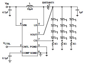
A simple white LED driver schematic can be created using the EL7513 constant current boost regulator, which is specifically designed for driving white LEDs. This driver can manage 4 LEDs in series or up to 12 LEDs in a...
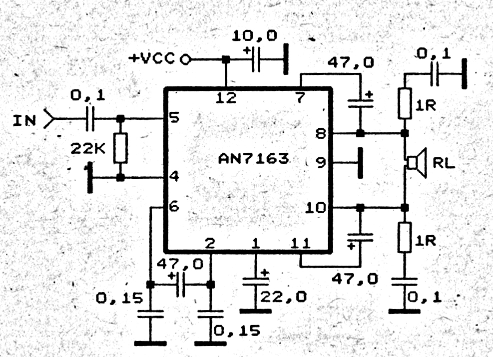
This 5.1 surround amplifier circuit schematic utilizes the IC AN7168 as the primary component. The circuit requires a minimum voltage of 12V and a maximum voltage of 24V, with a recommendation of 12V due to the voltage ratings of...
The power amplifier Hi-Fi OCL 120W RMS is designed to operate effectively when paired with a suitable power supply circuit and 8-ohm speakers. This circuit exclusively utilizes transistors without any integrated circuits, resulting in a clean sound output. The...
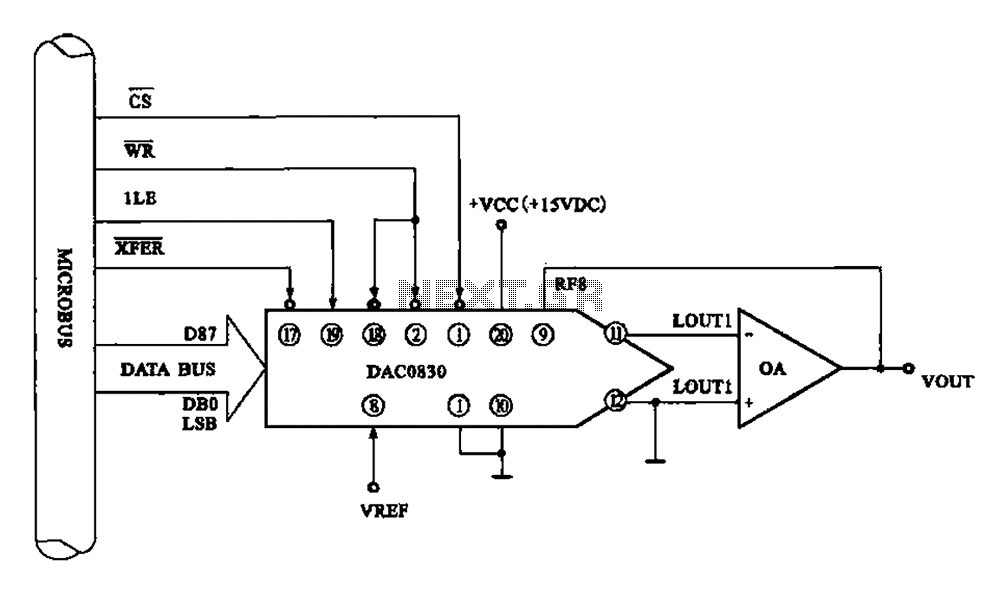
Figure 8 illustrates a typical digital-to-analog (D/A) conversion circuit that utilizes the DAC0830/DAC0832 chip. The microprocessor outputs an 8-bit digital signal, which is converted into an analog signal. The D/A conversion circuit depicted employs the DAC0830/DAC0832, which is a dual...
This page features H-Bridge circuits used for controlling direct current motors. Several designs are shown using both CMOS and Bi-Polar power devices. These circuits could be used as the basis for Model Railroad DCC Boosters or PWM motor controllers....
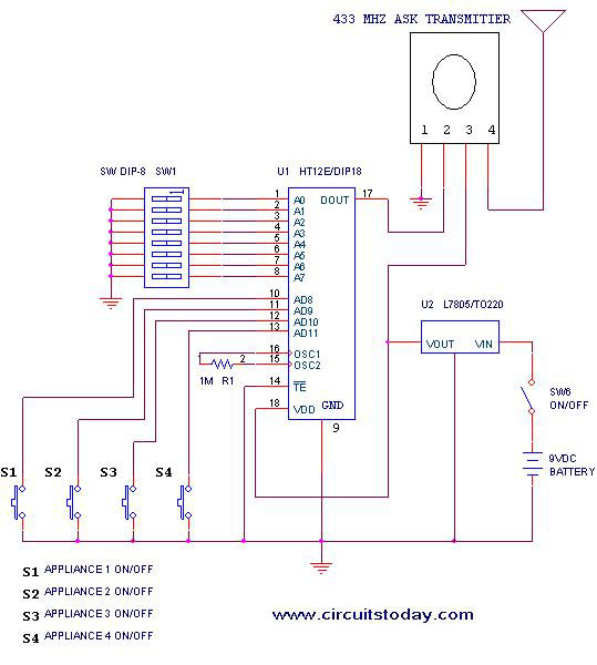
This project outlines a simple remote control system utilizing RF communication without the use of a microcontroller. The remote is designed for various home appliances such as televisions, fans, and lights, providing significant convenience by allowing operation from a...