
Electronics Grasshopper using 555

The Electronics Grasshopper project utilizes two NE555 timer ICs configured as astable multivibrators to create an audio output that mimics the sound of insects. The first timer (IC1) operates at a lower frequency and generates a sawtooth waveform, which is essential for modulating the second timer (IC2). The output of IC1 is connected to pin 5 of IC2, which is the control voltage input. This configuration allows IC1 to influence the frequency of IC2's oscillation, effectively creating a variable audio output.
The output from IC2, which operates at a higher frequency, is fed to a speaker via capacitor C4. This capacitor serves to block any DC component from the output, allowing only the AC audio signal to pass through. The resulting sound is a series of high-frequency pulses that can be perceived as a shrill "PI-PI" sound, similar to that of a grasshopper.
Resistors and capacitors in the circuit determine the time intervals for the oscillations of both timers, which can be adjusted to change the pitch and tone of the sound produced. The design is straightforward, making it suitable for educational purposes, as it provides a practical demonstration of oscillators, modulation, and sound generation principles in electronics. This project not only serves as an engaging activity for children but also enhances their understanding of basic electronic components and circuit design.Here is another fun project for children as well as electronics beginners. We often hear the sound of grasshopper or cockroach (i. e. shrill sound) at night. The project published in this website Electronics grasshopper produced PI-PI sound (sound like grasshopper) and can be used as doorbell. The entire circuit of electronics grasshopper is build around pair of timer IC (NE555) followed by few passive component (resistor and capacitor). Both the timer IC (IC1 and IC2) is used here as astable multivibrator. The frequency of IC1 is used to modulate the frequency of IC2 which further given to speaker from pin 3 of IC2 through capacitor C4. The modulation frequency of IC1 is obtained as saw tooth voltage at pin 6 given to control pin 5 of IC2 in order to control frequency of IC2.
IC1 is low frequency oscillator where IC2 is high frequency oscillator. The saw tooth voltage at control pin 5 of IC2 make output audio frequency (3 30 KHz) high and low and listen as shrill sound of insect (pi-pi sound of grasshopper). 🔗 External reference
Related Circuits

This is a circuit design for a PWM speed control circuit for DC motor rotation. The circuit features two functions: Forward-Reverse operation and Regenerative Braking. The control is achieved using a MOSFET. The circuit allows for the control of...
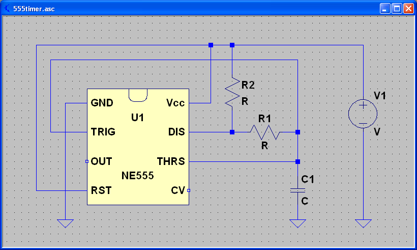
ECEN 2250 myDAQ Experiment Capacitors and the 555 Timer. The experiment involving capacitors and the 555 timer within the ECEN 2250 myDAQ framework focuses on understanding the behavior of capacitors in electronic circuits and the functionality of the 555 timer...
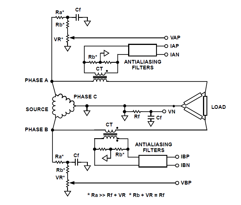
How can a circuit be built for digital readout of three-phase power consumption in a home using a chip like ADE7762? There is an interest in polyphase energy metering. To construct a circuit for digital readout of three-phase power consumption...
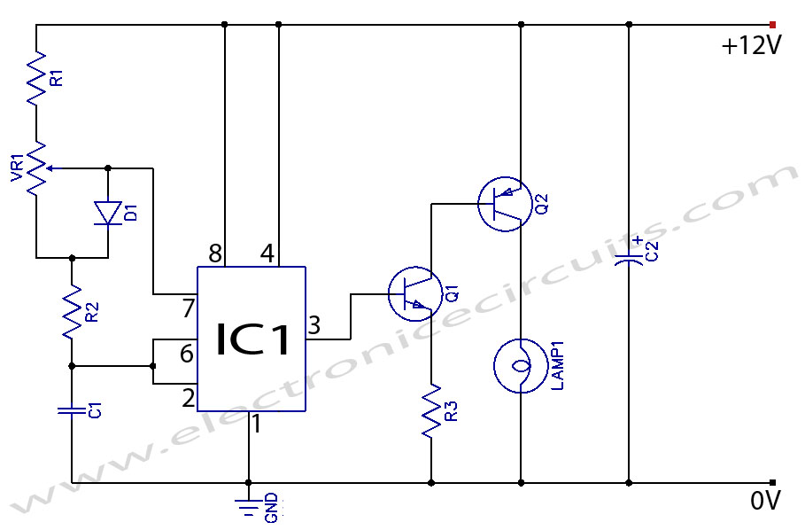
When the potentiometer is in the upper position, the capacitor charges rapidly through both 1k resistors and the diode, resulting in a brief positive interval and an extended negative interval, which dims the lamp to near darkness. Conversely, when...
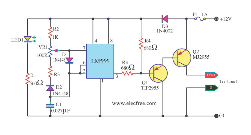
This circuit is a DC dimmer circuit that utilizes the LM555 integrated circuit configured as an astable multivibrator. It is capable of adjusting the duty cycle by fine-tuning variable resistors VR1 and VR2. The DC dimmer circuit employs the LM555...
The SE555/NE555 timer was first introduced by Signetics Corporation around 1971. The pin connections and their functions are as follows: Pin 1 (Ground) is the most-negative supply potential and is typically connected to circuit common when powered by positive...