
PWM Speed Control Circuit Using Forward-Reverse and Regenerative Braking

The PWM speed control circuit for a 12V DC motor is designed to enhance motor control capabilities by incorporating features such as Forward-Reverse operation and Regenerative Braking. The core of the circuit utilizes the Power MOSFET IRF150, which is capable of handling high currents and voltages, making it suitable for driving the motor efficiently.
The PWM signal, generated by a microcontroller or a PWM generator, modulates the gate of the IRF150, allowing for precise control over the motor's speed. By adjusting the duty cycle of the PWM signal, the effective voltage and current supplied to the motor can be varied, resulting in smooth acceleration and deceleration.
Relay RY1 plays a crucial role in enabling reverse operation. When activated, it switches the polarity of the voltage applied to the motor, allowing it to rotate in the opposite direction. This relay is also integrated with a digital alarm system that provides feedback on the operational status of the motor, alerting the user to any anomalies.
Relay RY2 is responsible for implementing regenerative braking, which recovers energy during the deceleration of the motor. When the motor is switched from forward to reverse or when the PWM signal is reduced significantly, the relay engages a brake resistor that dissipates the excess energy, preventing damage to the circuit and improving efficiency.
Fuse F1 is a safety feature that protects the circuit from overcurrent conditions. It can interrupt the power supply in case of a fault, ensuring the safety of the entire system. The digital alarm can also be configured to provide visual or audible alerts when the fuse is blown or when the motor encounters an operational issue.
Diode D1 is included in the circuit to protect against back EMF generated by the motor when it is turned off or when it experiences sudden changes in direction. This diode allows the current generated by the motor to safely dissipate, preventing potential damage to the MOSFET and other components in the circuit.
Overall, this circuit design offers a robust solution for controlling the speed and direction of a DC motor while incorporating safety features to enhance reliability and performance.This is a circuit design for PWM Speed DC Motor Rotation circuit. This circuit has two functions, Forward-Reverse and Regenerative Braking function. This circuit is control by MOSFET. This is the figure of the circuit; On this circuit, we can control the speed of DC 12V motor with Power MOSFET IRF150 using a signal PWM. The Relay RY1 work as contr ol Reverse with the digital alarm, change Q10. The Relay RY2 work as function brake resistor. The F1 use to protect through the circuit by control Run or stop with the digital alarm. D1 is used to protect the current turn back from DC motor. 🔗 External reference
Related Circuits
Hello everyone, I am not well-versed in electronics, so I would appreciate it if someone could create a diagram for me. I would like to modify a circuit so that it can dial a number using speed dial and...
The impedance of these current generators is essentially infinite for small currents, and they maintain accuracy as long as VIN is significantly greater than VOS and IO is much higher than I bias. The source employs a FET to...
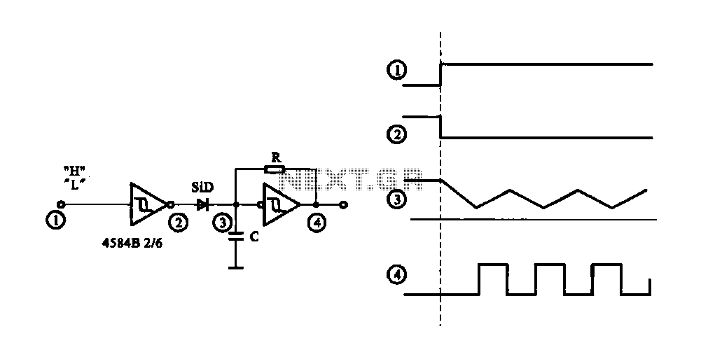
The circuit generates a controlled pulse signal. When a high pulse signal is applied to the input terminal O (start), the output pulse signal is activated. Conversely, when a low signal is received at the input terminal O (stop),...

This is a simple basic design of a servo motor controller with a pulse generator. It utilizes the CMOS IC 7555 in astable mode to generate pulses for driving the motor. The servo motor controller circuit employs the CMOS IC...
The first reverberator presented is based on the TDA1022, which is the most commonly used BBD (Bucket Brigade Device). Adjustments for proper functionality of the reverberator are required before connecting the power supply. The TDA1022 is a versatile BBD that...
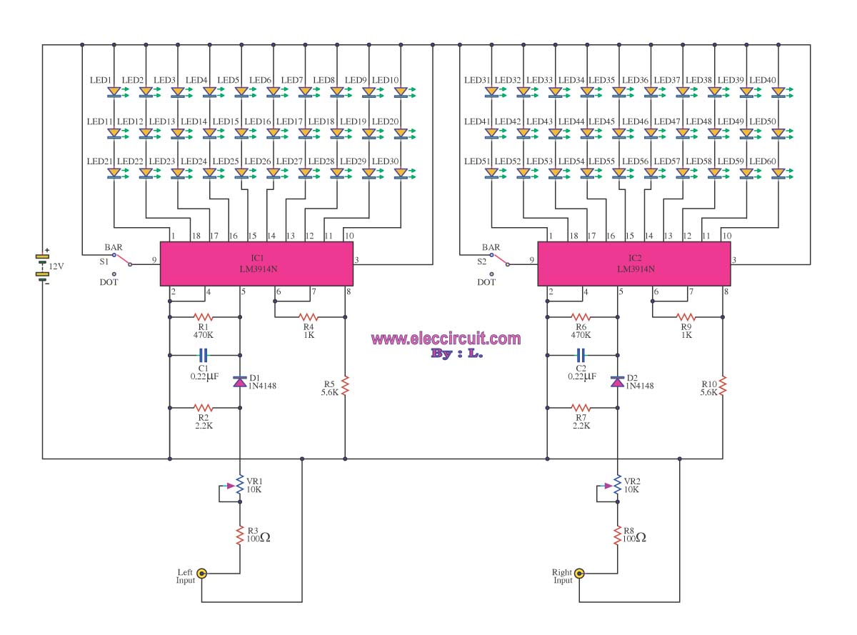
A VU meter is utilized to display the power level of audio signals and also serves as an aesthetic element. When purchasing a VU meter kit from an electronics store, options include assembling various parts independently or selecting a...