
Eliminate loops cold junction compensation amplification circuit ISO102 INA101

The described circuit employs an ISO102 isolation amplifier in conjunction with an INA101 instrumentation amplifier to effectively manage the challenges associated with thermocouple signal processing, particularly in environments where ground loops may introduce noise and inaccuracies. The K-type thermocouple, known for its wide temperature range and reliability, serves as the primary sensor, detecting temperature variations in the environment.
The INA101 plays a crucial role in amplifying the low-level voltage signal generated by the thermocouple. The gain of the INA101 is adjustable through the resistor Rc, allowing for flexibility in signal amplification based on specific application requirements. This capability is essential for optimizing the circuit's performance, especially in applications where precise temperature measurements are critical.
Following the amplification stage, the ISO102 isolation amplifier provides electrical isolation, which is vital for protecting sensitive components from potential voltage spikes and ground loop interference. The design ensures that the secondary ground of the ISO102 is at the same potential as the K-type thermocouple, effectively mitigating ground loop issues that could otherwise distort the temperature readings.
The inclusion of a 1N914 diode for cold-junction compensation is a standard practice in thermocouple applications. This diode helps to adjust the output signal to account for variations in the reference junction temperature, thereby enhancing the accuracy of the temperature measurement. The use of high-value resistors in the circuit further aids in maintaining stability and minimizing thermal drift, ensuring reliable performance over time.
Overall, this circuit configuration exemplifies a robust solution for accurate temperature measurement using K-type thermocouples, particularly in industrial settings where ground loops and environmental noise may otherwise compromise data integrity. As shown in FIG constituted by ISO102 and INA101 have to eliminate ground loops, and high-end off cold junction compensation thermocouple amplifier. This circuit uses the K-typ e thermocouple temperature detected at the scene, the temperature signal is converted to a voltage signal after amplification instrumentation amplifier INA101 to ISO102, ISO102 after the isolation amplifier output. Wherein the resistance Rc for setting INA101 gain. The characteristics of this circuit is interfering K-type thermocouple and ISO102 secondary ground is connected, that the formation of the same potential, thereby eliminating ground loops caused.
Using 1N914 diode as thermocouple cold-junction compensation, lM resistors high off circuit.
Related Circuits
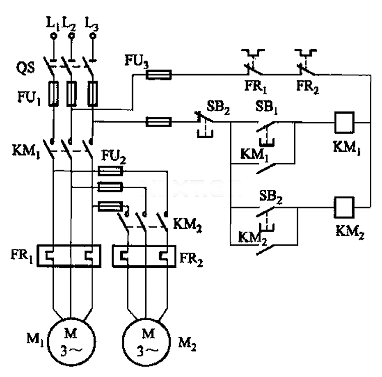
The circuit illustrated in Figure 3-83 demonstrates that the contactor KMi is activated only after it is pulled, which indicates that the motor Mi has started for the first time. Following this, the contactor KM2 is then activated, indicating...
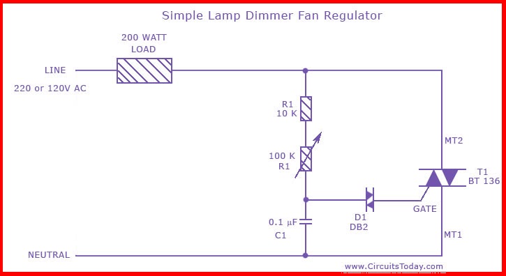
This is the circuit diagram of the simplest lamp dimmer or fan regulator. The circuit is based on the principle of power control using a Triac. The circuit operates by varying the firing angle of the Triac, which is...
A fluorescent tube is connected in an LC resonant circuit consisting of inductor L2 and capacitor C9. The bidirectional breakdown diode VD4 initiates the starting circuit. When AC power is applied, the gate potential of transistor VT2 increases due...
This is a game timer circuit diagram. When the game timer is reset, two actions must occur: the 4017 counter must return to zero, and the 4060... The game timer circuit utilizes the 4017 decade counter and the 4060 binary...

A simple battery charger designed for Nickel Metal Hydride batteries that require current-regulated charging. The charger delivers a charging current of 140 mA for efficient battery charging. The power supply section includes a 0-18 volt AC 1 Ampere step-down...

Having reliable connections is essential not only in daily life but also in electronics. Unlike social connections, the dependability of electrical contacts is crucial for the proper functioning of electronic devices. In the realm of electronics, the integrity of electrical...