
Emergency light

This circuit functions as an emergency lighting system that activates in the event of a power failure, ensuring safety and visibility in critical areas. The design employs a silicon-controlled rectifier (SCR), which is a semiconductor device that can be turned on by a gate signal and remains on until the power is removed.
When AC power is present, capacitor C1 charges through rectifier CR1 and resistor R1, creating a negative voltage at the gate of the SCR (C106Y). This negative voltage prevents the SCR from conducting, thereby keeping the emergency light off and allowing the battery to charge through rectifier CR2 and resistor R2. The charging process ensures that the battery remains ready to supply power when needed.
In the event of a power outage, capacitor C1 discharges quickly, causing the SCR to receive a triggering signal from the battery via resistor R3. This action turns the SCR on, allowing current to flow to the emergency light, which illuminates immediately. The design is efficient and requires no manual intervention, as the system is entirely automatic.
Once AC power is restored, the peak voltage from the AC line provides a positive bias to the SCR, turning it off and stopping the flow of current to the emergency light. Simultaneously, the circuit resumes the battery charging process, ensuring that the system is always ready for the next power interruption. The overall design minimizes maintenance requirements, making it suitable for installation in various environments where reliable emergency lighting is crucial.This simple circuit providers battery operated emergency lighting instantaneously upon failure of the regular ac service. When line power is restored, the emergency light turns off and the battery recharges automatically. The circuit is ideal for use in elevator cars, corridors and similar places where loss of light due to power failure would be undesirable.
Completely static in operation, the circuit requires no maintenance. With ac power on, capacitor CI charges through rectifier CRI and resistor Rl to develop a negative voltage at the gate of the C106Y SCR By this means, the SCR is prevented from being triggered, and the emergency light stays off. At the same time, the battery is kept fully charged by rectifier CR2 and resistor R2. Should the ac power fail, CI discharges and the SCR is triggered on by battery power through resistor R3. The SCR then energizes the emergency light. Reset is automatic when ac is restored, because the peak ac line voltage biases the SCR and turns it off.
Related Circuits
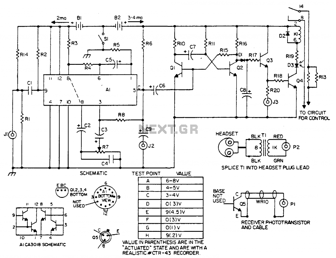
The laser light detector employs a sensitive phototransistor (Q5) positioned at the focal point of a lens (LE2). The output from Q5 is directed to a sensitive amplifier composed of an array (A1), which is biased through a voltage...
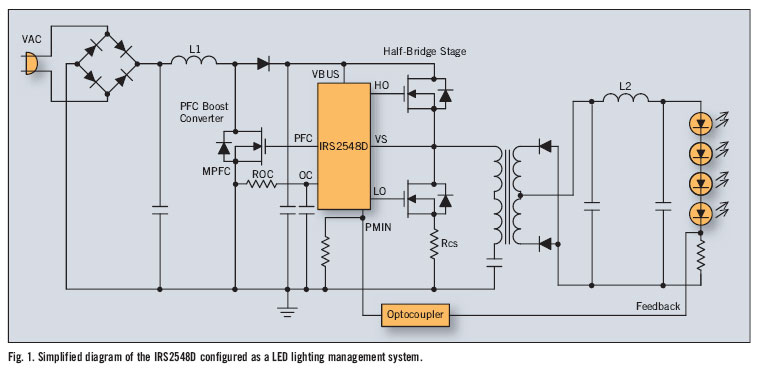
There is significant sensitivity to operating costs when managing high-powered commercial lighting. In these applications, there is a heightened focus on energy efficiency and AC line power factor, as these parameters influence operating expenses. Electric utilities impose additional charges...
In many instances, the dimmer described here may be integrated into a wall-mounted box that also contains the light switch. It is designed specifically for use with 240 V incandescent lamps. Upon activation, the lamp does not reach full...
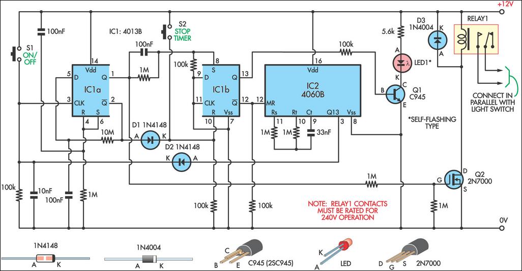
This 9-minute timer switch can be utilized to control lighting in a toilet or bathroom. The timer is activated by pressing switch S1 and deactivated by pressing S1 again. If the timer is not manually turned off, the light...
With RFT illuminated, point R goes to 0 volt and LM runs. With LFT illuminated, point R goes to 0 volt and RM runs. With RFT and/or LFT not illuminated, points R/L go to +9 volt; P1 and P2...
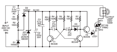
Components such as resistors R1 and R2, capacitors C1, C2, and C3, diodes D1 and D2, and a zener diode ZD1 are utilized to create a stable 5V DC supply voltage that delivers the necessary current to operate the...