
Switch Timer For Bathroom Light

The circuit operates as follows: upon pressing switch S1, the first flip-flop (IC1a) toggles its state, which in turn energizes FET Q2. This action activates the relay, allowing current to flow to the light fixture. If S1 is pressed again within the designated period, IC1a toggles back, deactivating FET Q2 and turning off the relay, thus cutting power to the light.
Should the user desire continuous lighting without the timer, pressing S2 within the 9-minute timeframe disables the timing function, allowing the light to remain on until S1 is pressed again. This feature is particularly useful in scenarios where extended illumination is required without the risk of the light turning off unexpectedly.
The 4060 oscillator/divider (IC2) provides the timing mechanism for the circuit. It generates a clock signal that is divided down to create the desired 9-minute timing interval. This timing is set by external resistors and capacitors connected to pins 9, 10, and 11, which determine the frequency of the oscillator. The relay used in this circuit should be capable of handling the load of the light fixture while being rated for 250VAC operation to ensure safety and reliability.
In summary, this timer switch circuit effectively combines user control with automatic timing features to manage lighting in a bathroom setting, enhancing convenience while minimizing energy waste. The integration of flip-flops, an oscillator, and a relay allows for a straightforward yet effective design suitable for various applications.This 9-minute timer switch can be used to control the light in a toilet or bathroom. The timer is started by pushing S1 and stopped by pushing S1 again. If you forget to turn it off, the controlled light will go off after nine minutes. If you need the light on continuously non-stop, you need to press S1 (turn on) and then S2 (cancellation of timer ) within 9 minutes and in this case the light will be on until you switch it off with S1. IC1 is a is 4013 dual flip-flop. Flip flop IC1a is toggled on and off by switch S1 and it controls the relay which is switched by FET Q2. IC1a controls IC1b which is connected as an RS flipflop to enable or disable IC2, a 4060 oscillator/divider.
This has its timing interval set by the components at its pins 9, 10 & 11. The relay should have 250VAC mains-rated contacts and these are connected in parallel with an existing wall switch. 🔗 External reference
Related Circuits
The circuit diagram presented illustrates an IC-controlled emergency light with a charger, functioning as a 12V to 220V AC inverter circuit. This emergency light circuit is designed to automatically activate in the event of a mains failure, while also...
This circuit can be utilized as a replacement for the single current-limiting resistor typically found in inexpensive battery chargers. The alternative presented here will prove beneficial over time, as it eliminates the need to discard NiCd batteries after a...
Turns off your amplifier when idle for 15 minutes. Fed by amplifier tape-output. This circuit turns off an amplifier or any other device when a low-level audio signal fed to its input is absent for 15 minutes at least....
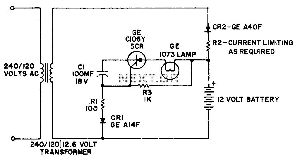
This simple circuit provides battery-operated emergency lighting instantaneously upon failure of the regular AC service. When line power is restored, the emergency light turns off and the battery recharges automatically. The circuit is ideal for use in elevator cars,...
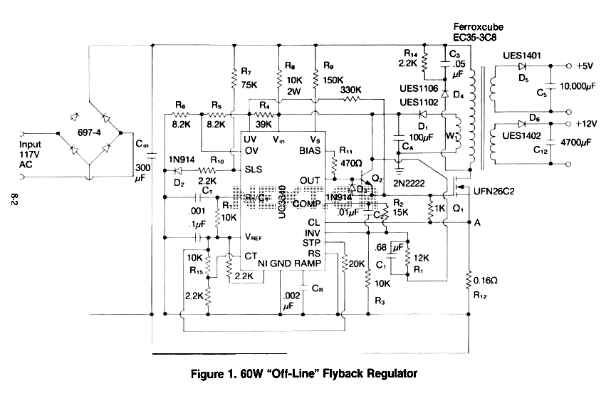
This paper gives a practical example of the design of an off-line switching power supply. Factors governing the choice of a discontinuous flyback topology are discussed. The design uses a pulsed-width modulation (PWM) control scheme implemented with a Unitrode...
Without a dedicated buck converter or white LED driver IC, it is possible to safely drive multiple standard high-efficiency white LED modules using available battery power. To design a circuit capable of driving high-efficiency white LED modules without a dedicated...