
Sun Light Chaser

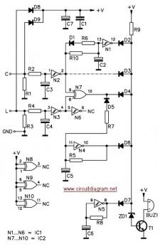
The described system appears to be a light-sensitive control circuit utilizing two photo-transistors or photo-resistors, labeled as RFT (Right Front Transistor) and LFT (Left Front Transistor). When RFT is exposed to light, it activates a corresponding control mechanism, causing point R to transition to 0 volts. This action initiates the operation of LM (Left Motor or Load). Similarly, when LFT is illuminated, point R again drops to 0 volts, activating RM (Right Motor or Load).
In the absence of illumination on both RFT and LFT, both points R and L revert to a high state of +9 volts, indicating a standby or inactive condition for the motors. The functionality of the system is further refined by the inclusion of two control points, P1 and P2, which are employed to set the threshold levels for the activation or deactivation of RM and LM. These control points likely consist of variable resistors or potentiometers that allow for fine-tuning of the sensitivity of the circuit to light levels.
To prevent interference between the two photo-sensitive components, it is crucial to implement a physical barrier, such as a vertical cardboard wall, between FT1 and FT2. This barrier is designed to create a shadow effect, ensuring that the illumination of one sensor does not inadvertently trigger the other, thus maintaining the integrity of the system's operation.
In summary, the described circuit is a light-activated control system for motors, utilizing photo-sensitive components and adjustable thresholds to manage the operation of two distinct loads based on light detection. The careful placement and isolation of the sensors are essential for optimal performance.With RFT illuminated, point R goes to 0 volt and LM runs. With LFT illuminated, point R goes to 0 volt and RM runs. With RFT and/or LFT not illuminated, points R/L go to +9 volt; P1 and P2 controls threshold point when RM/LM stop or start running. Remember to seperate FT1 and FT2 with a vertical cardboard wall in order to produce a shadow over the other FT whenthe first is illuminated by a lateral incident light.
🔗 External reference
Related Circuits
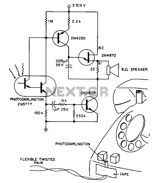
A 2N5777 photo-Darlington cell detects blinking light from transparent plastic buttons. A high-gain 2N3904 transistor is used to switch the power ON and OFF. The circuit can remain continuously connected to a 9 V battery, drawing less than a...
This circuit serves as a decorative element or indicator, featuring adjustable flashing or dancing speeds of LEDs and the ability to create various light patterns. It consists of two astable multivibrators: one formed by transistors T1 and T2, and...

This circuit controls a searchlight-type signal head and produces solid red, yellow, or green indications. The signals can be connected for normal or approach-type lighting of the green signal. The circuit utilizes an LM556 dual timer IC in a...
It allows car headlights to flash on and off simultaneously or alternately. Components: 555 IC, transistor, resistor, relay, polarized capacitor. The circuit utilizes a 555 integrated circuit (IC) in a monostable or astable configuration to control the flashing of car...
This is an automatic light dimmer circuit that eliminates the need for manual adjustment of light levels. It utilizes a Light Dependent Resistor (LDR) to detect ambient light conditions, which in turn controls a Triac to adjust the brightness...
The circuit is designed to ensure that the headlights or side lights are automatically switched off after the ignition contact is turned off. This prevents the occurrence of a dead battery due to headlights being inadvertently left on. The circuit...