
Emergency lighting circuit diagram

The circuit described functions as an automatic power backup system, utilizing a relay and transistors to manage the transition between power sources. The primary power source is 220V AC, which powers lamp H1 under normal operating conditions. The LSE (likely a low-voltage sensor or controller) monitors the voltage levels and provides an output signal that controls the transistor VT.
When the AC power is present, lamp H1 serves as an indicator light, signaling normal operation. The high output from the LSE keeps the transistor VT in a non-conductive state, which means that relay J remains deactivated. Consequently, lamp H2, which acts as the backup light, remains off.
During a power outage, the sudden loss of AC voltage causes lamp H1 to extinguish. The LSE detects this drop in voltage and its output signal transitions to a low state. This change turns on transistor VT, which then conducts and activates relay J. The relay, upon being energized, connects the power supply to lamp H2, causing it to illuminate automatically. This seamless transition between lamps ensures that there is minimal disruption in lighting, which is particularly important in critical situations such as surgeries.
The design of this circuit emphasizes reliability and simplicity, making it suitable for applications where continuous lighting is essential. The use of a relay provides a robust method for switching between power sources, while the transistor acts as an efficient control element, allowing for quick responses to changes in power availability. Overall, this automated system enhances safety and operational continuity during power interruptions.The device circuit works shown in Figure 11. Power outages are frequent thing, but some occasions, the power does not allow (such as the ongoing surgery, etc.). LSE with simple circuit design, fully automated. When 220V AC, the lamp H1 lights up, while the LSE feet high output, transistor VT end, the relay J is released, it does not shine direct light H2. Once a power outage, H1 off, LSE's pin output low, then transistor VT conduction, the relay J pull, turn the power lights H2, H2 light automatically convert between almost two lights interruption.
Related Circuits

This circuit is designed to automatically adjust the brightness of lights based on the ambient light intensity. In bright conditions, the lights remain off, while in low ambient brightness, the lights are activated. The circuit incorporates a thyristor (VT1)...

The circuit diagram represents an enhanced lock system, the AE1169, which is an upgrade of the AE1168 model. When the lock button is pressed, the AE1168 utilizes a keyboard scanning method to identify the corresponding button. Based on the...

When the preset is set to its maximum, the LED flashes at a rate of approximately once every half second. This rate can be increased by raising the capacitor value from 10µF to a higher value. For instance, if...
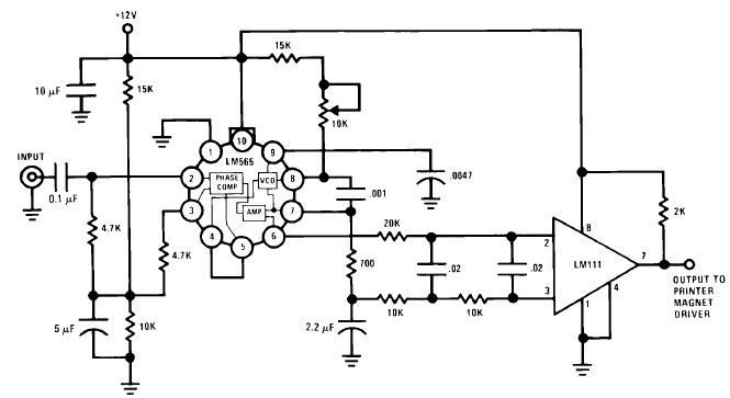
A simple Frequency Shift Keying (FSK) demodulator for 2025 Hz and 2225 Hz can be designed using the LM565, a general-purpose phase-locked loop integrated circuit. This IC includes a stable, highly linear voltage-controlled oscillator that provides low distortion FM...
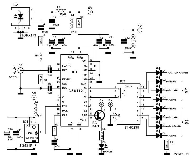
The S/PDIF monitor is an application of the digital audio interface receiver Type CS8412 from Crystal. Previous articles have covered the decoding of S/PDIF (Sony/Philips Digital Interface Format) into data, bit clock, and L/R clock for use in devices...

A neon lamp can easily be added to the phone line to act as a ring indicator. It is perfect for times when you cannot hear the phone. The integration of a neon lamp as a ring indicator in a...