
Ethernet Controller with PIC18F452

The described circuit utilizes a PIC18F452 microcontroller to serve as an Ethernet controller, allowing for remote management and monitoring via a web interface. The system is designed to control eight outputs, which can be activated or deactivated through commands received over the Ethernet connection. This capability is particularly useful for applications requiring remote operation of devices or systems.
The circuit employs three timers, each associated with a dedicated buffer, to manage the timing of the outputs. Each timer can be independently configured with specific start and stop times, enabling precise control over the operation of the outputs. The timers are linked to buffers, with Buffer 1 controlling Timer 1, Buffer 2 controlling Timer 2, and Buffer 3 controlling Timer 3. The values stored in the buffers dictate the state of the outputs, allowing for dynamic adjustments based on user input from the web interface.
In addition to output control, the system integrates a DS1820 temperature sensor for temperature monitoring. This sensor is capable of providing real-time temperature data, which can also be transmitted via the web interface. This feature enhances the functionality of the circuit, making it suitable for applications where environmental monitoring is critical.
The circuit includes a DS1307 real-time clock (RTC) module, which is powered by a backup battery to ensure timekeeping even during power outages. The RTC provides accurate time and date information, which can be displayed on the web interface and utilized in the control logic for the timers and outputs.
Overall, this Ethernet-controlled circuit is a versatile solution for remote management of outputs and monitoring of environmental conditions, with the added benefit of web-based adjustments and configurations. The integration of timers and buffers allows for complex timing operations, while the inclusion of temperature sensing and real-time clock functionality enhances its applicability across various domains.This circuit is an ETHERNET controller I use the PIC18F452 and the mikroC C Compiler. I use also the JAVA SCRIPT information you can get from www.w3school.com I Control 8 outputs throw the WEB and transfer time information also. I use 3 timer and 3 buffers each one has it?s own time Start ? Stop and the outputs will take the buffer BIN value. BUFFER 1 -> TIMER 1 . BUFFER 2 -> TIMER 2. BUFFER 3 -> TIMER 3. I do all the adjustment throw the WEB. I also test it to transfer temperature information using DS1820 temp. Sensor. I Set time-date throw the WEB. Features: 1. Display time (DS1307), with backup battery. 2. Control 8 outputs 3. 3 timers to control the outputs each timer has separate time for start and stop 4. All the adjustment throw the WEB 🔗 External reference
Related Circuits
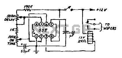
This 12V wiper speed controller circuit utilizes a 555 timer. It is a straightforward and practical circuit that can be installed in any car. The 12V wiper speed controller circuit is designed to regulate the speed of windshield wipers in...
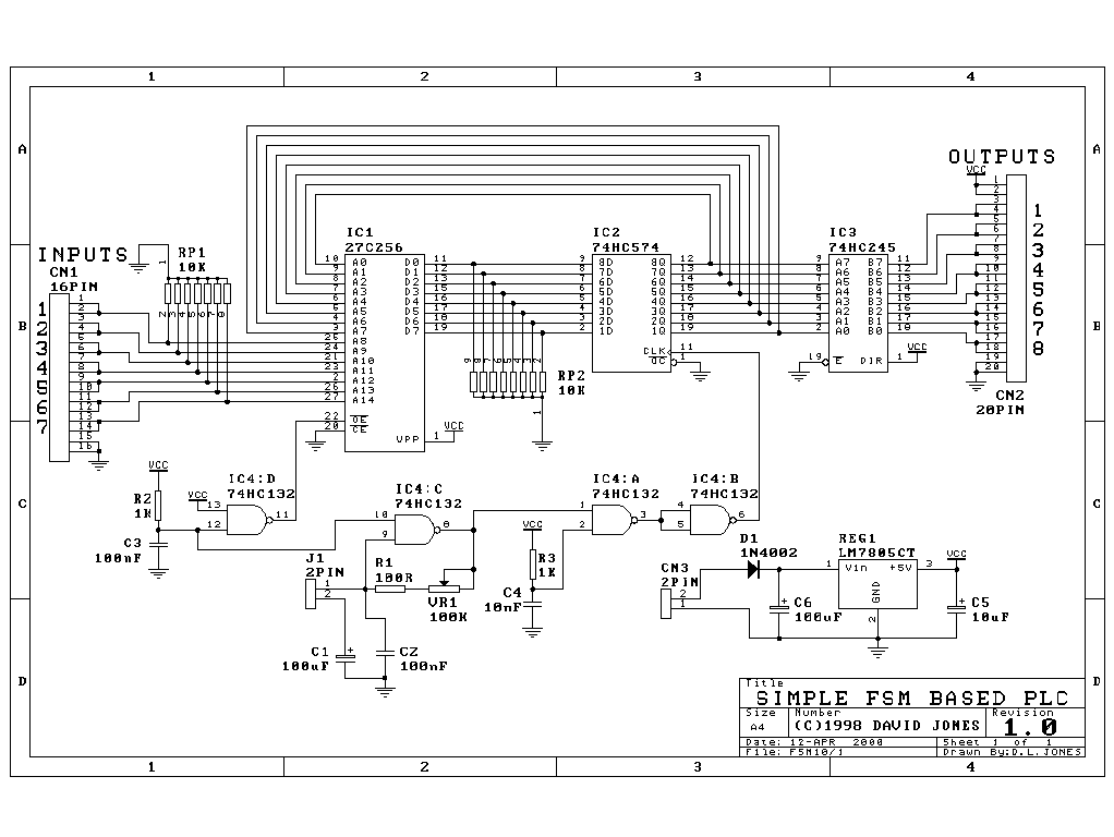
I have had this project hanging around for ages and have tried to submit it for publication without much enthusiasm so I will make everything available here for the individual constructor. The complete Pascal source code for the compiler...
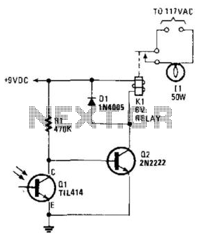
A phototransistor detects daylight. At dusk, it stops conducting, and Rl biases Q2, activating Kl, which turns on the light. At dawn, Ql begins to conduct, cutting off Q2. Kl deactivates, and the light turns off. The circuit utilizes a...
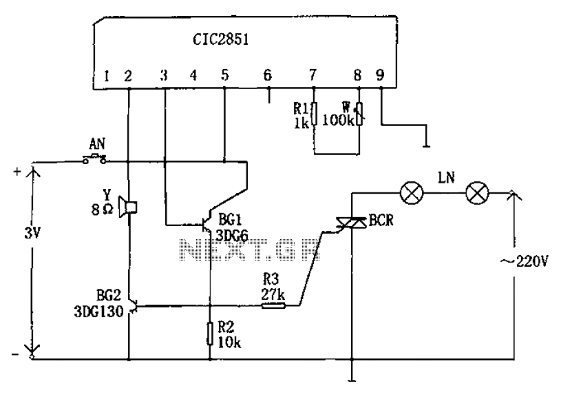
The non-contact lantern control circuit includes an integrated music IC (CIC2851), transistors (BG1 and BG2), a thyristor (SCR), and other components. When the switch is pressed (AN), the CIC2851 is activated, causing the output terminal (pin 3) to emit...
The rectifier bridge voltage is determined by the U2 element; refer to its datasheet for the maximum voltage specifications. The minimum voltage at this pin should not fall below approximately 9V, or 6.5V if low-dropout type U2 and U3...
The widespread application of Flash technology in microprocessors has led to significant advancements in the development and utilization of one-chip computers. Designers have transitioned from traditional in-circuit emulators (ICE) and JTAG interfaces to more cost-effective and user-friendly development methods....