
Microcontroller Voltmeter / Ammeter with LCD

The rectifier bridge circuit is crucial for converting alternating current (AC) to direct current (DC), and it is typically composed of four diodes arranged in a bridge configuration. The voltage specifications for the U2 element should be strictly adhered to in order to ensure reliable operation. The use of low-dropout voltage regulators allows for efficient voltage regulation, particularly in applications where space and heat dissipation are considerations.
In the context of the power supply unit (PSU), the current sense shunt resistor provides feedback for measuring the load current, enabling accurate monitoring and control of the circuit's performance. This feedback is essential for applications requiring precise current regulation, such as in battery management systems or power distribution networks.
The programming of the microcontroller is facilitated through the LCD connector, which serves as a communication interface. Utilizing an old PC HDD cable for this purpose is a cost-effective solution that maintains compatibility with standard programming tools. It is critical to ensure that the microcontroller is powered correctly during programming, as any voltage discrepancies can lead to programming failures or damage to the device.
The brown-out detection feature is a vital safeguard that prevents the microcontroller from operating under insufficient voltage conditions, which could lead to erratic behavior or data corruption. The recommended threshold of 4V for the brown-out reset ensures that the microcontroller resets safely when the supply voltage drops below this level.
The design of the PCB should accommodate both normal and mirrored versions, allowing for flexibility in manufacturing. The choice of connector for the LCD module should prioritize ease of replacement and future upgrades, ensuring that the system can evolve with changing requirements.
Safety precautions are paramount when working with mains-powered circuits. Adequate measures, such as wearing rubber-soled shoes and maintaining a safe posture, help mitigate the risks associated with electrical shock. Thorough verification of circuit connections before energizing the system is essential to prevent accidents and damage to components.Rectifier bridge voltage. See U2 element you used data sheet to know about maximum voltage it can work properly. On the other hand the minimum voltage on that pin mustn`t drop bellow c. a. 9V, or 6. 5V if low drop type U2 and U3 voltage regulators were used. Multimeter is suitable for voltage and current measurement in PSU, where current sense shunt resistor is connected in series with load and is in negative rail. Because µC is in TQFP package, we can program it after soldering all the elements on PCB. It makes programming quite easy to perform. Programming signals are delivered through LCD connector. To make the programming cable, you can use old PC HDD cable. Picture of my programming cable is shown below. Remember, that during programming multimetr circuit must be supplied with +5V. Depending on your programmer, supply voltage is provided either by programmer, or from separate power supply unit. After connecting µC to prog, you should check, if µC is "visible" for prog. When everything is fine, you can upload code to µC. The code is available here. It is assumed here, that µC is new and works with its internal RC clock at 1MHz. If not, set appropriate fusebits to archive above mentioned conditions. In addition Brown-out detector should be turned on by enabling BODEN fuse. Recommended Brown-out Reset Threshold Voltage is 4V. The next thing to do is to cross LCD soldering pads number 1 and 5. It is necessary to provide ground for LCD RW signal. After all, connect LCD module with the multi meter PCB. It is recommended to use a detachable connector for further expandability e. g. software upgrading. Picture of PCB is here. There are two version of PCB - normal and mirrored. I think, that anyone who makes PCBs will know, which one should be used to produce right PCB. * DO NOT work if you are tired or in a hurry, double check every thing before connecting your circuit to the mains and be ready to disconnect it if something looks wrong.
* When you are testing a circuit that works off the mains wear shoes with rubber soles, stand on dry non conductive floor and keep one hand in your pocket or behind your back. 🔗 External reference
Related Circuits

In previous posts, a schematic for interfacing a keypad and LCD using the 8051 architecture was presented. This blog post details the complete implementation of the interface using the AT89S51 microcontroller with programming in assembly language. It is assumed...
A milliamp meter can be utilized as a voltmeter by incorporating a series resistance. The required resistance is calculated by dividing the full-scale voltage reading by the full-scale current of the meter movement. For example, using a 1 milliamp...
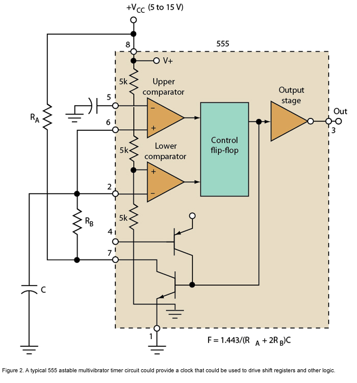
Micro or analog? These days, it is becoming increasingly challenging to make a choice. The 555 timer has long been regarded as a benchmark for flexibility. How does it perform today? The 555 timer IC, originally introduced in 1972, remains...
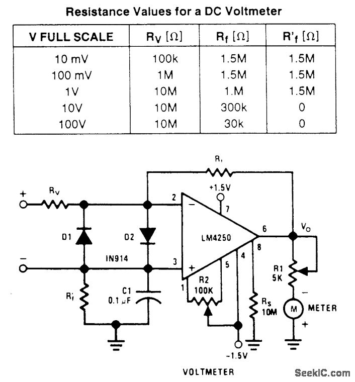
A wide-range voltmeter circuit. This inverting amplifier has a gain varying from -30 for the 10-mV full-scale range to -0.003 for the 100-V full-scale range. Diodes D1 and D2 provide complete amplifier protection for input overvoltages as high as...

The following circuit illustrates the AD8531 integrated circuit used for the automatic control of LCD panel backlighting. Features include the ability to compensate for aging effects and other functionalities. The AD8531 is a precision operational amplifier known for its low...
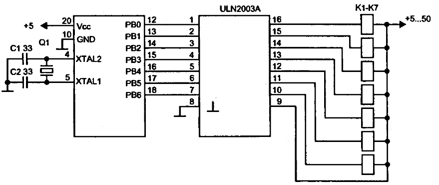
To drive a relay, a current greater than 20mA is required, which cannot be supplied by a single microcontroller pin. Therefore, a relay cannot be connected directly to a microcontroller pin. Instead, a simple amplifier circuit consisting of a...