
Exit Sign With Battery Protection

The circuit design incorporates two Luxeon 1W Star LEDs, which are mounted in a manner that optimizes their directional light output for visibility in emergency exit situations. The LEDs are powered by a 6V sealed lead-acid battery, which is a common choice due to its reliability and cost-effectiveness in backup power applications. The circuit includes a monitoring feature that ensures the battery does not fall below a critical voltage level.
Transistors Q1 and Q2 are configured as switches that control the power supplied to the Luxeon LEDs. When the battery voltage exceeds the set threshold of 5.5V, the transistors remain in the "on" state, allowing current to flow to the LEDs and providing sufficient illumination. The adjustment of VR1 allows for fine-tuning of the voltage threshold, accommodating variations in battery performance and ensuring optimal operation.
The circuit also includes a low-power consumption mode that activates when the battery voltage drops below 5V. In this state, the current drain is minimized to below 200 µA, preserving battery life and preventing damage from deep discharge. This feature is critical, as it extends the operational lifespan of the SLA battery, especially in scenarios where the mains power supply may be interrupted for extended periods.
Overall, this circuit effectively balances the need for adequate illumination in exit signs with the necessity of protecting the battery from over-discharge, ensuring reliable performance in commercial environments.This circuit substitutes two white Luxeon 1W Star LEDs for the inverter and fluorescent tube in a standard battery-backed illuminated exit sign, as used in commercial premises. While the Luxeons have less light output than a standard small fluorescent tube, their directional light is quite adequate for the purpose and they do result in less curren
t drain from the battery. However, the use of a 6V SLA battery for this application means that it can be completely discharged if the 240VAC mains supply is absent for a long period, as can happen when the power to vacant premises is switched off. Such a complete discharge will effectively destroy the battery and must be avoided. This circuit achieves this by switching off Q1 & Q2 when the battery voltage falls below 5. 5V, as set by trimpot VR1. For voltages below 5V, the current drain falls to below 200 µA. 🔗 External reference
Related Circuits
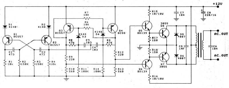
This circuit is a 100W DC inverter based on a transistored multivibrator and serves as a transistor signal amplifier. The inverter converts a 12V DC input voltage to approximately 220V AC. It is recommended to use a 12V car...
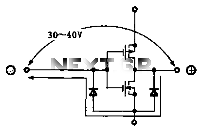
Due to the varying conditions of different input signals, when an abnormal voltage is applied to the pin, protection circuits are designed to create a circuit path that secures the internal protection of large-scale integration (LSI) circuits. The structure...
In certain video applications, signal sources provide RGB signals along with a composite sync signal. The RGB signals do not include video sync. On the receiving end, some budget video decoders lack a separate composite sync input; they only...

This circuit was designed to control power delivery to a Peltier cooler in a vehicle. The power to the load from the vehicle's battery is managed by a Single Pole Double Throw (SPDT) relay. The circuit utilizes an SPDT relay...
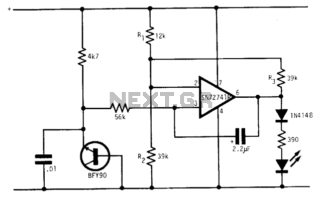
Under optimal battery conditions, the LED remains off. As the battery voltage decreases, the LED starts to flash, and when the battery reaches a low voltage condition, the LED illuminates continuously. This circuit is designed for use with a...
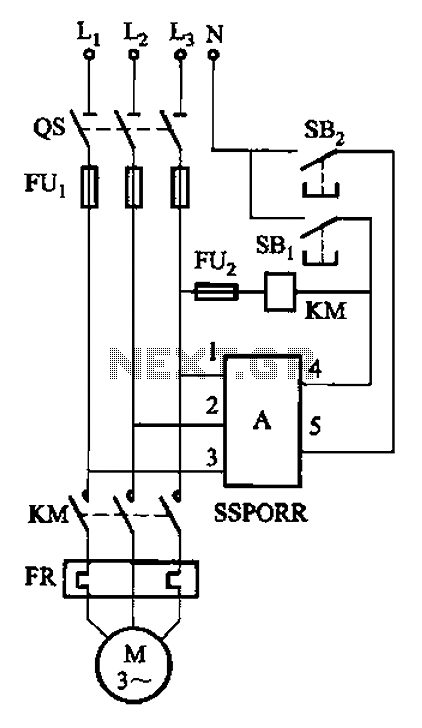
The solid-state phase failure relays for three-phase AC phase failure monitoring, protection, and control of new devices are referred to as SSPORR. This module consists of a five-terminal semiconductor configuration. Terminals 1, 2, and 3 serve as the three-phase...