
Various protection circuit structure and working principle diagram

The protection circuit for LSI devices is essential for safeguarding the integrity of the integrated circuit against voltage spikes and other anomalies that may occur during operation. The circuit typically consists of several key components, including diodes, resistors, and capacitors, which work together to divert excess voltage away from sensitive components.
When an abnormal voltage is detected at the input pin, the protection circuit activates. Diodes are often employed in a clamping configuration to redirect excessive voltage to ground, effectively limiting the voltage that reaches the LSI. This prevents damage that could result from transient voltages or electrostatic discharge (ESD).
The resistors in the circuit can serve multiple purposes, such as current limiting and voltage division, ensuring that the voltage levels remain within safe operating ranges. Capacitors may also be included to filter out high-frequency noise, providing additional stability to the circuit.
Overall, the design of the protection circuit must take into account the specific voltage levels and signal characteristics of the application. Proper selection of components and configuration is crucial to ensure reliable operation and to extend the lifespan of the LSI device. This protective mechanism is a vital aspect of modern electronic design, particularly in environments where signal integrity and reliability are paramount.Due to the different circumstances of the various input signals, when the pin is applied between the abnormal voltage, protection circuits to form a circuit path from while LSI (large scale integration) circuits internal protection. Structure and principles of its protection circuit is shown
Related Circuits

Often, there is a need for an additional telephone ringer in an adjoining room to be alerted about incoming calls. For instance, if the telephone is situated in the drawing room, an extra ringer may be required in the...
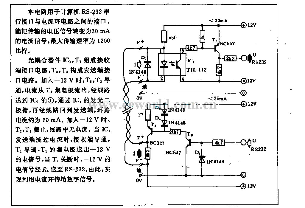
This circuit is utilized in RS-232 serial interface and current loop circuit applications. It converts voltage signals into a 20mA current signal, with a maximum transmission rate of 1200 bits per second. The CCD IC1 and transistor T1 form...
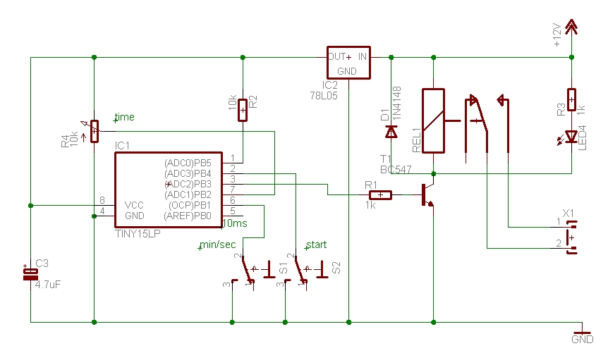
The time can be set using a potentiometer ranging from 1 minute to 1023 minutes, approximately 17 hours. A pushbutton initiates the timing process, activates a relay, and the timer will deactivate the relay once the set time has...
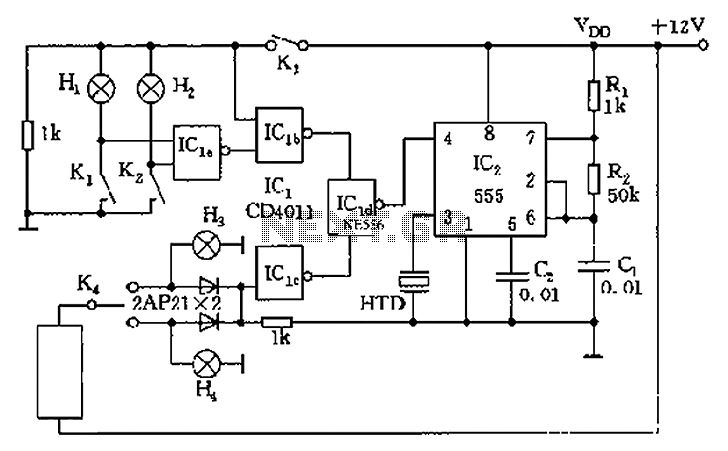
The circuit presented is a 555 timer-based alarm system for vehicles, which primarily consists of a 555 timer and a quad 2-input NAND gate configuration. It is designed to produce a long beep sound when oil pressure is low...
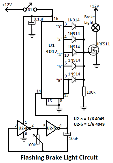
This flashing brake light circuit is designed for motorcycles. When the brake light switch S1 is closed, power is supplied to U1 and U2. The circuit utilizes two inverters from U2. The flashing brake light circuit operates by utilizing a...
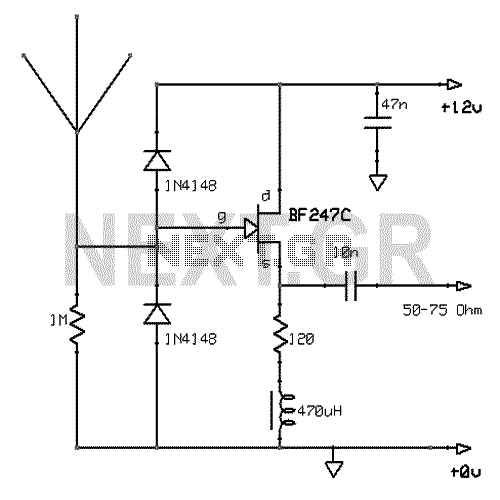
This active antenna schematic can be used to frequency range from 10 KHz to 100 MHz. The length of the Antenna can be between 0.5 to 1 meter long. The power consumption is 20-30mA. More: Use the shortest possible...