
F232 is USB powered

The F232 is a USB interface device that facilitates communication with RS232 systems. To ensure proper signal levels between the F232 and the RS232 interface, a level translator is essential. The F232 outputs a digital signal compatible with USB standards, which typically operates at lower voltage levels than those required by RS232. The MAX232 is a commonly used integrated circuit that converts TTL (Transistor-Transistor Logic) levels to RS232 voltage levels, allowing for effective communication between the two systems.
In this configuration, the Tx pin of the F232 is connected to the input of the MAX232, which then translates the signal to the appropriate RS232 levels. The design also incorporates a power supply arrangement that ensures the MAX232 receives sufficient voltage to operate correctly. This is particularly crucial because the RS232 standard requires higher voltage levels for signal integrity over longer distances.
For the receive (Rx) side, the use of an opto-isolator can provide electrical isolation between the F232 and the RS232 device, protecting both devices from potential voltage spikes or ground loop issues. The opto-isolator converts the RS232 signal back to TTL levels that the F232 can interpret.
The modification to replace the original RS232 chip with the MAX232 enhances the reliability and performance of the circuit. The MAX232 is favored for its ability to operate with a low supply voltage while still conforming to RS232 standards. The circuit layout, while not based on FTDI’s provided Gerber files, maintains compliance with necessary electrical specifications, ensuring that the custom design functions effectively within the intended application.
Overall, the integration of the F232 with the MAX232 level translator creates a robust solution for interfacing USB devices with RS232 systems, facilitating seamless communication and data transfer between disparate technologies.F232 is USB powered, but you need to have a level translator at the output of F232. Tx of f232 has to be converted to RS232 levels, since the other side has a max. Receive pin can be easily opto-ed. But the transmit pin, need to have a supply in line with RS232 levels. Sometimes we d it by making a higher supply from the remote RS232 chip - a comm on method, if you are in control of the remote max pin. Here is the circuit. I modified the circuit to replace rs232 chip with MAX232 to the board sold by FTDI guys. FTDI has got circuit + gerbers in their site. I did not use their gerbers. Got a layout made by someone. 🔗 External reference
Related Circuits
A PoE Plus power level of 30 W can be achieved by utilizing an external MOSFET along with a controller that is compatible with the older standard. Power over Ethernet (PoE) technology enables the delivery of electrical power along with...
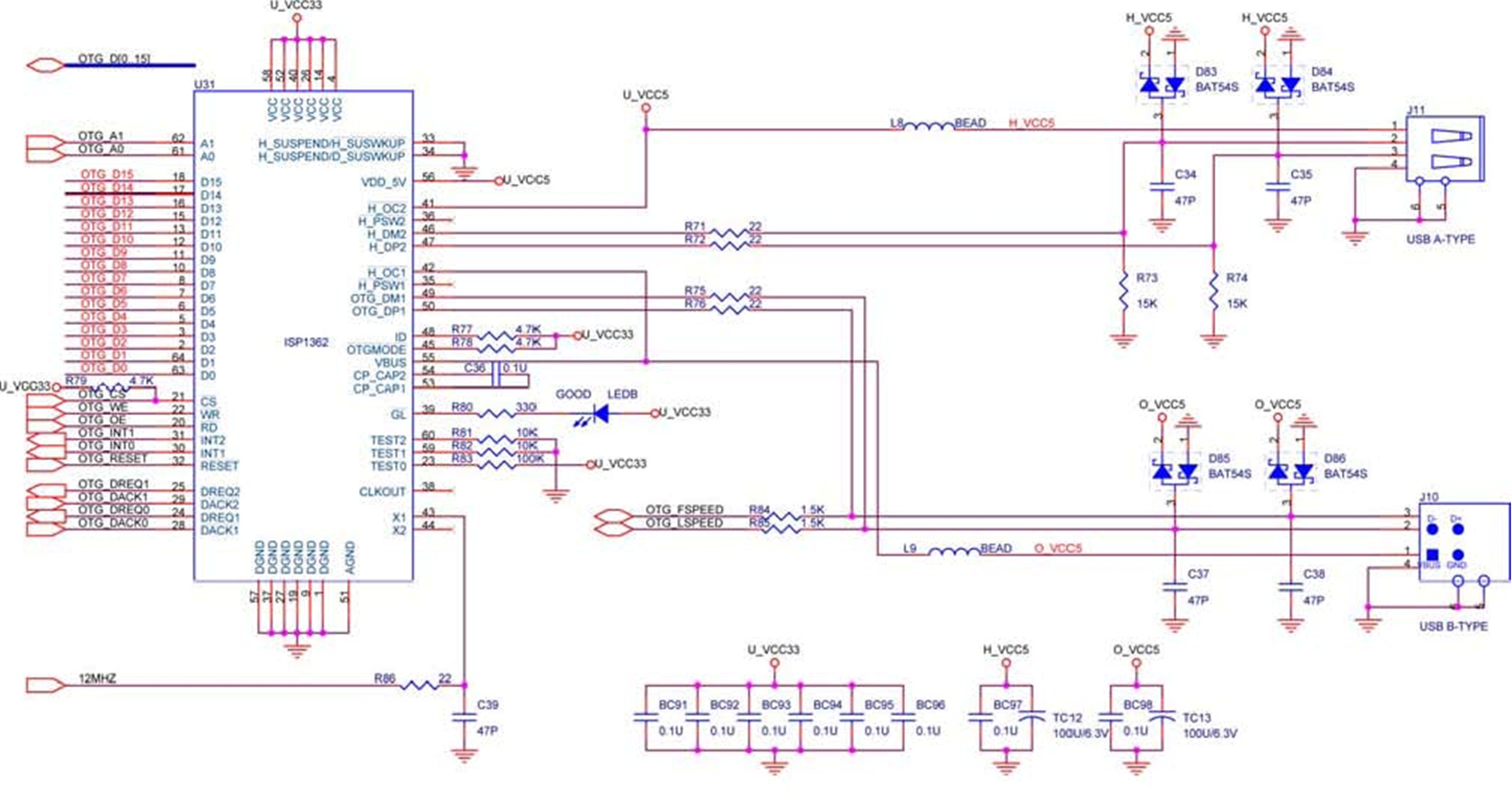
The DE2 board features both USB host and device interfaces utilizing the Philips ISP1362 single-chip USB controller. The host and device controllers adhere to the Universal Serial Bus Specification Revision 2.0, enabling data transfer at full-speed (12 Mbit/s) and...
The USB charger power supply is designed for use in MP3 and MP4 chargers. It accepts an input of AC 160-240V at 50/60Hz and has a rated output of DC 5V at 250mA. For applications requiring a long-term higher...

LCD2USB is an open source/open hardware project. The goal of LCD2USB is to connect HD44780 based text LCD displays to various PCs via USB. LCD2USB was meant to be cheap and to be made of easily available parts. It...
The i2c-tiny-usb project is an open source/open hardware project. The goal of i2c-tiny-usb is to provide a cheap generic i2c interface to be attached to the usb. It is meant as a replacement for those simple and cheap printer...
To share a regional press like the USB printer, scanner etc. two computers, it is relatively easy. Just connect the two computers on a network device and say the printer as shared. This method however requires the continued operation...