
Fading LedsCircuit

The described circuit employs a triangular wave generator using two operational amplifiers to create a pulsing effect for two LED strips. The operation of the circuit is based on the principle of alternating current flow to each strip, which allows one strip to illuminate while the other dims, creating a visually appealing effect.
The configuration of IC1, which houses the operational amplifiers, is crucial as it generates the triangular waveform necessary for the pulsing action. The triangular wave's characteristics—frequency and amplitude—can be modified by adjusting the timing components, specifically resistors R4 and R5 in conjunction with capacitor C1. By varying these components, the user can set the desired pulsing frequency, thus customizing the visual output of the LED strips.
The constant current source circuit, composed of transistors Q1, Q2, Q5, and Q6, ensures that each LED strip receives a consistent current of 10mA, which is essential for maintaining uniform brightness and preventing damage to the LEDs. The driver transistors Q3 and Q4 are responsible for switching the LED strips on and off in response to the triangular wave signal, effectively controlling the pulsing action.
Resistors R7 and R8 play a pivotal role in adjusting the brightness of the LEDs. By modifying the resistance values, the current flowing through the LEDs can be increased or decreased, allowing for fine-tuning of the luminosity to suit specific aesthetic preferences or requirements.
Overall, this circuit design provides a versatile solution for creating dynamic lighting effects with LED strips, suitable for various applications such as decorative lighting, mood lighting, or as part of a larger electronic project.This circuit operates two LED strips in pulsing mode, i. e. one LED strip goes from off state, lights up gradually, then dims gradually, etc. while the other LED strip does the contrary. Each strip can be made up from 2 to 5 LEDs at 9V supply. The two Op-Amps contained into IC1 form a triangular wave generator. The rising and falling voltage obtain ed at pin #7 of IC1 drives two complementary circuits formed by a 10mA constant current source (Q1, Q2 and Q5, Q6) and driver transistor (Q3 and Q6). R4, R5 & C1 are the timing components: the total period can be varied changing their values. R7 & R8 vary the LEDs brightness. 🔗 External reference
Related Circuits
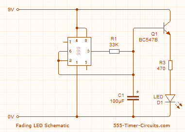
These two circuits create a fading effect for an LED. The first circuit charges a 100µF capacitor, and a transistor amplifies the current entering the capacitor, delivering 100 times this value to the LED through the collector-emitter pins. The...
This circuit operates two LED strips in pulsing mode, where one LED strip transitions from an off state to gradually lighting up, then dimming, while the other LED strip performs the opposite action. Each strip can consist of 2...
This circuit is used to slowly illuminate and fade a pair of red LEDs (light emitting diodes). The fading LEDs could be installed as 'eyes' in a small pumpkin or skull as a Halloween attraction, or mounted in a...

This circuit is designed to gradually illuminate and fade a pair of red LEDs (light-emitting diodes). The fading LEDs can be used as 'eyes' in a small pumpkin or skull for Halloween decorations, or as part of a Christmas...
LED sequencer that follows the rhythm of music or speech, powered by a 9V battery, is a portable unit. The basic circuit illuminates up to ten LEDs in sequence, following the beat. The LED sequencer circuit operates by detecting audio...

This circuit operates two LED strips in pulsing mode, i.e. one LED strip goes from off state, lights up gradually, then dims gradually, etc. while the other LED strip does the contrary. Each strip can be made up from...