
Fahrenheit Thermometer Using LM35 Temperature Sensor IC

The described temperature-to-voltage adapter is designed to convert temperature readings into corresponding voltage outputs, suitable for interfacing with digital voltmeters. This adapter typically employs a temperature sensor, such as a thermocouple or thermistor, which generates a voltage that varies with temperature changes.
To implement this circuit, the temperature sensor is connected to a signal conditioning stage, which may include an operational amplifier to amplify the small voltage signal produced by the sensor. The output from the signal conditioning stage is then fed into the digital voltmeter.
The high input impedance of the voltmeter ensures that it does not load the sensor output, allowing for accurate temperature readings without affecting the sensor's performance. The millivolt resolution of the voltmeter enables precise measurements, making it suitable for applications requiring fine temperature resolution.
Additional components that may be included in the circuit are resistors for setting gain, capacitors for filtering noise, and possibly a microcontroller for digital processing if more complex functionality is desired. The design should also consider the temperature range of interest to select an appropriate sensor and ensure linearity in the voltage output across that range.
Overall, this setup allows for effective temperature monitoring and can be integrated into various applications, including HVAC systems, environmental monitoring, and industrial process control.If you have a digital voltmeter, or any voltmeter with millivolt resolution and high input impedance, then you can use this temperature-to-voltage adapter. 🔗 External reference
Related Circuits
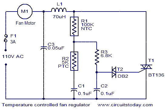
This fan regulator circuit automatically controls the speed of a fan based on temperature. It utilizes two thermistors (R1 and R2) for temperature sensing. The operation is similar to previously published designs, with thermistors replacing the potentiometer. As the...
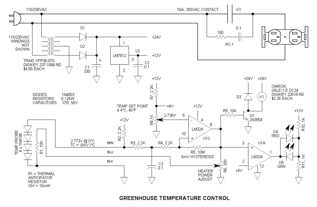
This circuit consists of four 1N4148 diodes connected in series with a thermal anticipation resistor (R1) heat-shrunk together at the end of a three-wire signal cable, which is visible in some photos. The thermal anticipation resistor is an old...
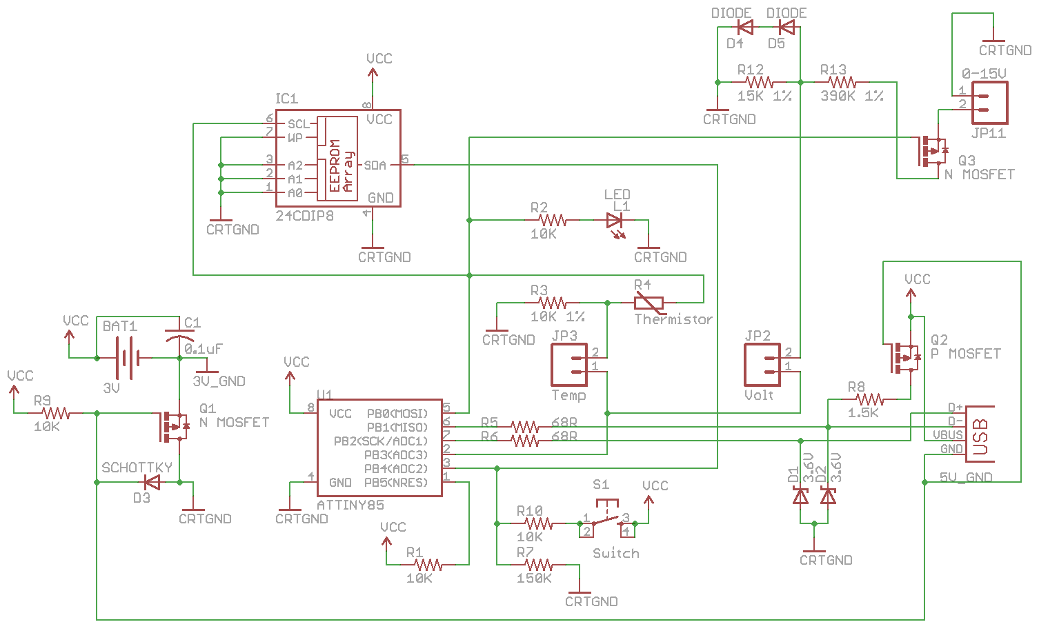
Combine the SATL and SAVL together. The schematic was updated with the voltage sensing circuit. A MOSFET was added to draw power from the voltage source only when needed. There are two jumpers, Temp and Volt, allowing the user...
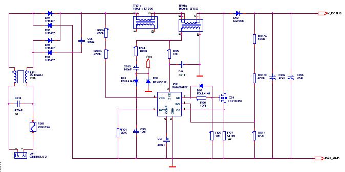
This article outlines a proposed solution for a 200 W power supply utilizing the FSFR2100 Fairchild Power Switch (FPS). The input voltage range is 90 to 265 VRMS, and it features six outputs. The 200 W power supply circuit based...

The circuit utilizes the LM35 temperature sensor to measure temperature in the range of 0 to 99 degrees Celsius and displays the readings using two seven-segment displays. It is designed to activate devices through the RC pins; for instance,...

This circuit is a 1024 kHz temperature-compensated crystal oscillator. The circuit theory is illustrated. Due to the low output signal level of the circuit, a buffer using the following transistor VT1 is implemented for amplification. The base bias resistor...