
Fast Electronic Fuse

The electronic fuse functions as a protective device in electrical circuits, designed to interrupt the flow of current when it exceeds a pre-set threshold. This specific fuse operates at an input voltage of 230V AC, making it suitable for standard household and industrial applications. The adjustable trip current feature allows users to set the desired current limit based on their specific load requirements, enhancing flexibility and protection for various devices.
The core components of the electronic fuse include a current sensing element, a microcontroller or comparator circuit, and a switching mechanism, often a relay or a MOSFET. The current sensing element continuously monitors the load current. When this current exceeds the adjustable trip level, the microcontroller processes this information and activates the switching mechanism to disconnect the load from the power source.
The adjustable feature is typically implemented using a potentiometer or digital input, allowing for precise calibration of the trip current. This ensures that the fuse can be tailored to protect sensitive electronics that may require lower trip currents, as well as more robust equipment that can handle higher currents without tripping unnecessarily.
In addition to its primary function of overcurrent protection, the electronic fuse may include features such as visual indicators (LEDs) to signal the operational status, as well as a manual reset option to restore functionality once the fault condition has been cleared. Some designs may also incorporate a delay mechanism to prevent nuisance tripping during transient conditions, such as inrush currents.
Overall, this fast electronic fuse represents an advanced solution for circuit protection, combining user adjustability with reliable operation to safeguard electrical systems effectively.A fast electronic fuse designed to operate on 230V AC with an adjustable trip current. When the current through the load exceeds a level determined by the.. 🔗 External reference
Related Circuits
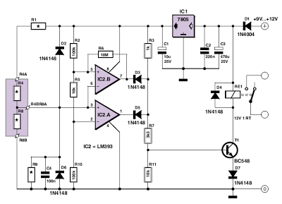
This circuit utilizes two comparators configured as a window comparator. Resistors R2, R5, and R10 establish a voltage window within which the voltage at the junction of D2 and D6 must reside for the outputs of IC2.A and IC2.B...
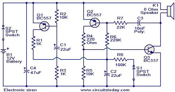
This is a compact electronic siren circuit based on three transistors. This circuit is suitable for incorporation with other alarm or siren projects such as burglar alarms, automatic factory sirens, or a simple push-to-on alarm. The electronic siren circuit...

The following diagram illustrates a straightforward electronic combination lock utilizing the IC LS7220. The component part list includes: C1 = 1µF 25V, C2 = 220µF 25V, R1 = 2.2K Ohm, Q1 = 2N3904 or 2N2222, D1 = 1N4148 or...
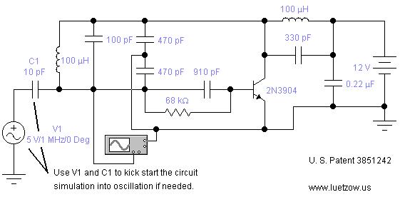
The oscillator circuits presented on this page are derived from expired or non-maintained U.S. Patents. All circuits are formatted for "Electronic Workbench 5.12" or "Multisim 7" circuit simulation software. A note regarding SPICE simulation of electronic oscillator circuits: all...
This circuit diagram represents a simple electronic combination lock using the CI LS7220 integrated circuit (IC). The circuit is designed to activate a relay for controlling a device based on a preset combination of four digits. It operates within...
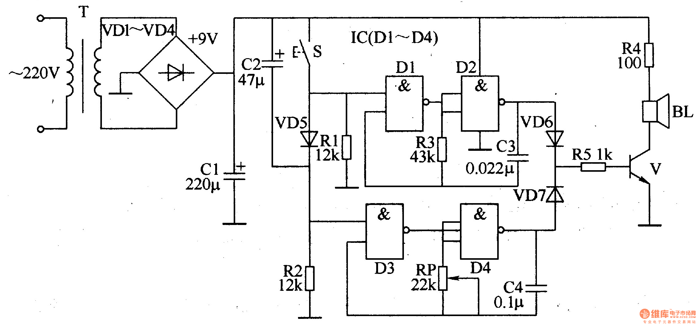
The ding-dong electronic doorbell circuit consists of a power supply circuit, a trigger control circuit, and an audio oscillator output circuit. The power supply circuit includes a power transformer (T), rectifier diodes (VD1-VD4), and a filter capacitor (C1). The...