
Fast Symmetrical Zener Clipper

This circuit design effectively resolves the limitations associated with traditional Zener diode configurations for symmetrical clamping. The inclusion of a diode bridge allows for improved voltage regulation, as it ensures that the same Zener voltage is consistently applied across the load. This is particularly advantageous in applications where precise voltage control is critical.
The diode bridge consists of four diodes arranged in a configuration that allows for bidirectional current flow. This arrangement facilitates the rectification of AC signals and ensures that the Zener diode operates within its optimal voltage range, thus minimizing the impact of voltage drops across the diodes. The reduced charge storage in the diode bridge is a significant improvement, as it mitigates the potential for delays in response time, which can be critical in fast-switching applications.
Biasing the Zener diode ON continuously enhances the sharpness of the knee in the Zener voltage characteristic. This results in a more defined transition between the breakdown region and the normal operating region, which is essential for achieving reliable clamping performance. The overall circuit design not only addresses the issues of voltage discrepancies and charge storage but also enhances the speed and accuracy of voltage clamping, making it suitable for a variety of electronic applications where stability and precision are paramount. The problem with using two zeners back to back in series to get symmetrical clamping is that the knee of the zener characteristics is rather sloppy. Also, charge storage in the zeners causes speed problems and the zeners will have slightly different knee voltages, so the symmetry will not be all that good. This circuit overcomes these problems. By putting the zener inside a diode bridge, the same zener voltage is always experienced. The voltage errors caused by the diodes are much smaller than those caused by the zener. Also, the charge storage of the bridge is much less. By biasing the zener ON all the time, the knee appears to be much sharper.
Related Circuits
The capacitor charges until the PNP transistor (here shown as a 2N3906, but you could also use a BC327) receives base current through the Zener and turns on. Then the NPN transistor (here shown as a 2N3904, but you...
This circuit utilizes a single 555 Timer IC and a small transformer to generate high voltage for testing zener diodes with voltage ratings up to 50VDC. The 555 Timer is configured in astable mode, with the output from pin...
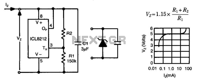
The ICL8212 is configured as a programmable zener diode, allowing for the programming of zener voltages ranging from 2 V to 30 V by appropriately selecting R2. The zener voltage is influenced by this selection. Additionally, due to the...
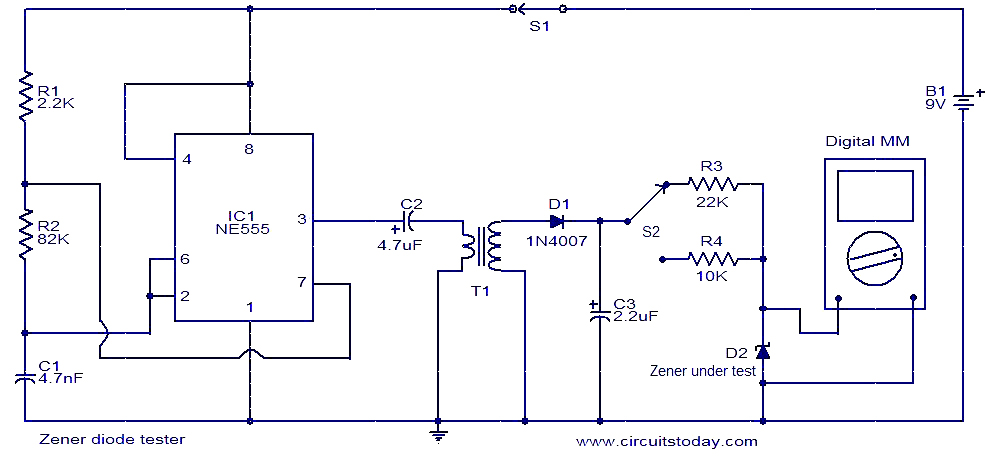
This circuit is designed for testing Zener diodes. The NE555 integrated circuit (IC1) is configured as an astable multivibrator, generating a square wave output. This output is transformed into a high voltage alternating current (AC) by transformer T1, with...
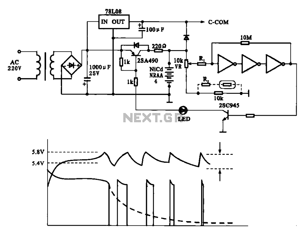
Fast charging circuit that illustrates voltage and current waveforms along with the configuration of the fast charge circuit for the charger. The detection and control circuit consists of three inverters (GMOS) from integrated circuits, enabling automatic control functions. The fast...
The response of an integrated circuit to fast transients on its input supply is a critical measurement. For micro-power devices that do not require an input bypass capacitor, a 50-ohm terminated function generator can be used to drive the...