
Feedback oscillator

The described circuit functions as an oscillator, utilizing a transistor to achieve phase shifting necessary for sustained oscillation. The transistor operates in a feedback configuration, where the output at the collector is fed back to the base, creating a condition for continuous oscillation. The 180-degree phase shift provided by the transistor is crucial as it ensures that the output signal is in opposition to the input signal, fulfilling the requirement for positive feedback.
To achieve the desired phase shift of 60 degrees for each RC network, the values of the resistors (R) and capacitors (C) must be selected carefully. The formula f = 1/(2πRC) is employed to calculate the resonant frequency (f) of the RC network. This frequency corresponds to the frequency of oscillation for the entire circuit. The choice of R and C values directly influences both the frequency and the phase shift characteristics of the oscillator.
In practical applications, the design may involve multiple RC networks, each contributing to the overall phase shift. The phase shifts must be precisely calculated to ensure that the total phase shift around the circuit sums to 360 degrees (or 0 degrees, equivalently), allowing for stable oscillations. The careful selection of component values will also affect the amplitude and stability of the oscillations, making it essential to consider the tolerances and characteristics of the components used.
Overall, the circuit's ability to oscillate is a result of the careful interplay between the transistor's phase shift and the RC networks' contributions, allowing for the generation of a periodic waveform at the desired frequency.Circuit oscillates because the transistor shifts the phase of the signal 180° from the base to the collector. Each of the RC networks in the circuit is designed to shift the phase 60° at the frequency of oscillation for a total of 180°
The appropriate values of R and C for each network is found from f = l/2Vr3TrRC); that equation allows for the 60° phase shift required by the design.
Related Circuits
A phase-locked loop (PLL) is widely utilized in telecommunications, control systems, and various other electronic applications. PLLs can be employed to demodulate frequency-modulated (FM) signals and generate a stable output frequency. A phase-locked loop is an essential feedback control system...
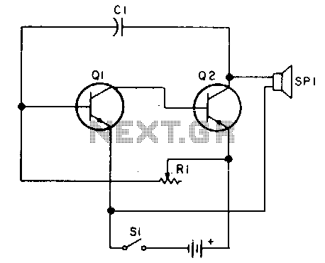
Oscillator, operates with 2 to 12 volts DC (optimal performance is achieved at 9 to 12 volts for maximum volume and clear keying). Additionally, R1 can be substituted with a 500K potentiometer, allowing the circuit to sweep across the...
The circuit is designed exclusively for fundamental crystals, as it lacks mode suppression components. The oscillator transistor Q104 remains in a cutoff state for most of the time, activating only briefly during the peak of the crystal current waveform....
A very simple DIY crystal oscillator circuit that uses a quartz crystal for frequency stability and a suitable RF transistor. It employs a second or third harmonic crystal for operation. This DIY crystal oscillator circuit is designed to generate stable...
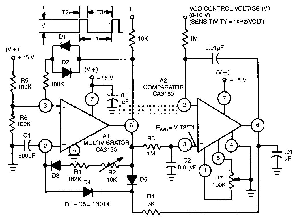
This circuit utilizes a CA3130 BiMOS operational amplifier as a multivibrator and a CA3160 BiMOS operational amplifier as a comparator. The oscillator exhibits a sensitivity of 1 kHz/V, with a tracking error of approximately 0.02% and a temperature coefficient...
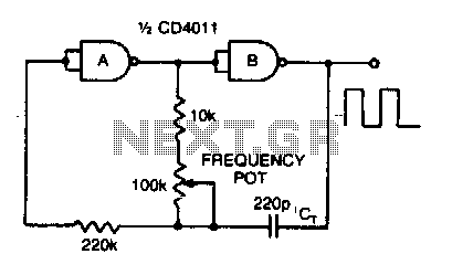
Adjusting the 100 K ohm potentiometer modifies the discharge rate of capacitor Ct, thereby affecting the output frequency. A square wave output is produced. The maximum frequency achievable with CMOS technology is constrained to 2 MHz. The circuit described involves...