
FET Audio Mixer and Switch

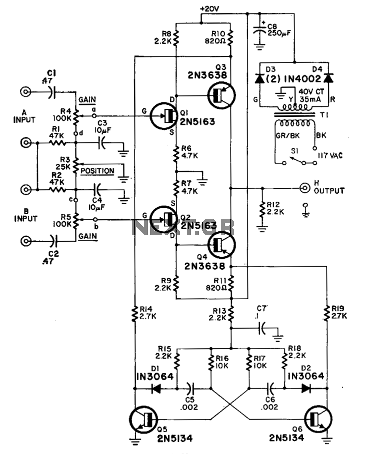
The FET audio mixer and switch circuit utilizes field-effect transistors (FETs) to achieve efficient audio signal mixing and switching. The circuit design incorporates various resistors (R1 to R7) and variable resistors (VR1 and VR2) to control gain and balance across audio channels. Capacitors (C1 to C6) are strategically placed to filter and couple audio signals, ensuring that the frequency response is optimized for both low-frequency (LF) and high-frequency (HF) applications.
The use of junction FETs, specifically the BF245 or 2N3819, is critical in this circuit due to their low noise characteristics and high input impedance, making them suitable for audio applications. The switches (S1 and S2) allow for manual selection between different audio sources or channels, enhancing flexibility in audio routing.
The circuit operates by allowing audio signals to pass through the FETs, which act as variable resistors controlled by the gate voltage. This configuration provides low distortion and high fidelity, essential for audio mixing applications. The values of the resistors and capacitors can be adjusted to tailor the circuit's performance to specific audio requirements, such as adjusting the mixing levels or the frequency response.
Overall, the FET audio mixer and switch circuit is a versatile design that can be adapted for various audio processing tasks, making it a valuable tool for audio engineers and enthusiasts alike.How to built a FET Audio Mixer and Switch Circuit. PARTS LIST, R1 1MΩ, R2 47kΩ, R3 47kΩ, R4 1MΩ, R5 47kΩ, R6 47kΩ, R7 47kΩ, VR1 50kΩ, VR2 50kΩ, C1, C2, C3 4.7µF 16V, C4 100nF (104), C5 47nF (473), C6 47nF (473), Q1 BF245 or 2N3819, Q2 BF245 or 2N3819, S1, S2 Switch, Junction-FETs such as the BF245 or 2N3819 already popular in HF circuits but it can also applied to LF circuits. 🔗 External reference
Related Circuits
A peak level indicator when a signal exceeds a certain maximum value. It can be quite useful, for instance, with tape recorders, mixing consoles etc. One of the most important requirements of a peak level indicator is that it...
The G9 project is an adaptation of the Gyratec IX dual microphone/line/DI preamplifier, tailored to meet the demands of DIY enthusiasts. A thorough search did not yield a complete design for a tube microphone preamplifier, prompting the decision to...
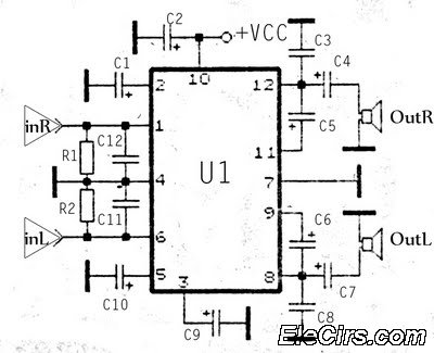
The KA2211 stereo audio power amplifier schematic is designed for electronics applications. This amplifier circuit provides a stereo output with a power output of 2 x 5.8 Watts at an impedance of 4 ohms. The frequency response ranges from...
Design and dimensioning of active low-pass and high-pass filters using Sallen-Key and multiple feedback topologies. Spice netlist generator. Active low-pass and high-pass filters are essential components in signal processing, allowing specific frequency ranges to pass while attenuating others. The Sallen-Key...
The switcher output connects to the single vertical input of the oscilloscope, while a sync line from one of the inputs is routed to the oscilloscope's external-sync input. The frequency response of the input amplifiers reaches 300 kHz across...

This touch switch does not rely on mains hum for switching; it can be used with battery-powered circuits. The Schmitt trigger IC1 forms a 100 kHz oscillator, and IC2a, which is biased into the linear region, amplifies the output...