
FET Audio Mixer circuit

The mixer circuit is designed to provide flexibility in channel configuration, allowing for an arbitrary number of input channels to be integrated into the system. Each input section typically consists of a preamplifier stage, followed by a mixing stage, where audio signals are combined. The schematic outlines the layout of these input sections, which can be replicated in a modular fashion.
In a typical implementation, each input section may include components such as resistors, capacitors, and operational amplifiers (op-amps) to ensure proper signal conditioning and mixing. The preamplifier stage is crucial for amplifying weak audio signals to a suitable level before they are mixed. The mixing stage may utilize summing amplifiers to combine multiple signals while maintaining signal integrity and minimizing distortion.
The design allows for scalability; when additional channels are required, the user can simply replicate the existing input section circuitry, ensuring uniformity in performance across all channels. This modularity is particularly beneficial in large-scale audio applications, such as live sound reinforcement or studio recording, where multiple sources need to be managed simultaneously.
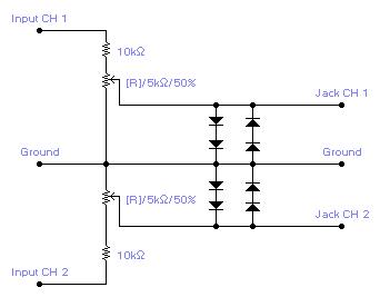
For practical implementation, attention must be paid to power supply requirements, grounding techniques, and signal routing to prevent interference and maintain audio quality. Proper layout techniques in the PCB design can further enhance performance by minimizing crosstalk between channels and ensuring stable operation across the mixer.As many or as few channels as are required can be added to the mixer. Do this by just duplicating the input "sections" which are clearly shown on the schematic. One version of this mixer I saw had 25 inputs! 🔗 External reference
Related Circuits
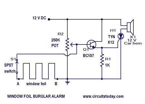
A simple burglar alarm circuit diagram and schematic. This can be used as an anti-theft alarm by attaching the burglar alarm circuit to window foil. The burglar alarm circuit is designed to provide a basic security solution for residential or...
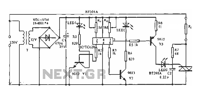
The circuit utilizes a built-in temperature sensor to control the triac TC620 for temperature regulation. The adjustment circuit consists of resistors Rp1 and Rn, which can be modified to set both the lower and upper temperature limits. LED1 illuminates...
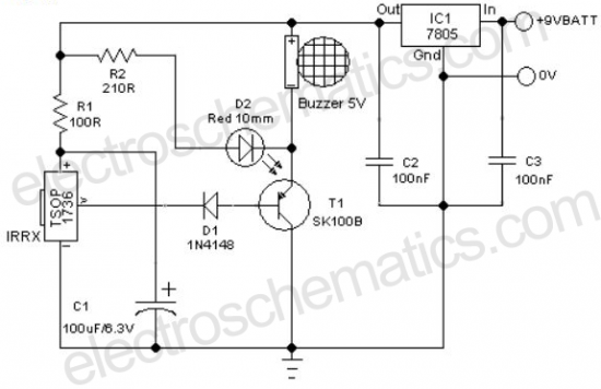
A remote-controlled alarm circuit utilizing the TSOP1736. This circuit involves routing an electric cable to connect a calling bell switch near the bed of an elderly individual. The remote-controlled alarm circuit designed with the TSOP1736 is an innovative solution for...
For simple electronic circuits, it may be sufficient to gain qualitative insights on dedicated electrical signals. This interface circuitry allows the line-in input of a standard PC sound card to be utilized as a 2-channel oscilloscope. Although this setup...
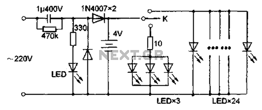
The circuit diagram depicted in Figure 5 illustrates a system for charging a lead-acid battery using 220V AC power. The circuit employs a capacitor, buck converter, and diode rectifier for this purpose. A red LED indicates the charging status....

This circuit is designed for tone control utilizing a three-band equalizer. It is based on the LF351 single-chip operational amplifiers. The circuit features three adjustable ranges: bass, mid, and treble controls. The equalizer allows for approximately +/-20 dB of...