
3 band equalizer circuit

The tone control circuit employs three separate bands to manipulate audio frequencies, allowing for enhanced sound customization. The LF351 operational amplifier is a versatile component known for its low noise and high performance, making it suitable for audio applications. Each band consists of a filter circuit that adjusts the amplitude of its designated frequency range.
The bass control adjusts low-frequency signals around 50 Hz, which is crucial for enhancing the depth and fullness of sound. The mid-range control targets frequencies around 1 kHz, which is essential for vocal clarity and instrument presence. The treble control modifies high-frequency signals around 10 kHz, adding brightness and detail to the audio output.
The circuit operates efficiently within a supply voltage range of 6 to 30 volts, providing flexibility for different applications. However, to achieve the maximum boost of 20 dB, the circuit must be powered with a supply voltage of 18 volts. This characteristic allows users to optimize the performance of the equalizer according to their specific audio requirements.
Component values are critical in determining the precise cutoff frequencies and gain levels for each band. Proper selection of resistors and capacitors in the feedback and input paths of the operational amplifiers will influence the overall performance of the equalizer. Additionally, careful layout and grounding practices are essential to minimize noise and ensure signal integrity throughout the circuit.
In summary, this tone control circuit with a three-band equalizer using LF351 op-amps provides a comprehensive solution for audio signal manipulation, enhancing the listening experience through adjustable frequency response tailored to user preferences.This is a circuit for a tone control using 3 band equalizers. This circuit is based on single chip op amps LF351. This circuit having three ranges, bass, middle and treble controls. This is the figure of the circuit; With a single chip op amps LF351, it is easy to make equalizer offers three ranges, low frequency, mid frequency, and high. With com ponent values shown there is approximately +/-20dB of boost or cut at frequencies of 50Hz, 1kHz and 10kHz. Supply voltage may be anything from 6 to 30 Volts. Maximum boost 20dB is only realized with maximum supply voltage of 18 Volt. 🔗 External reference
Related Circuits
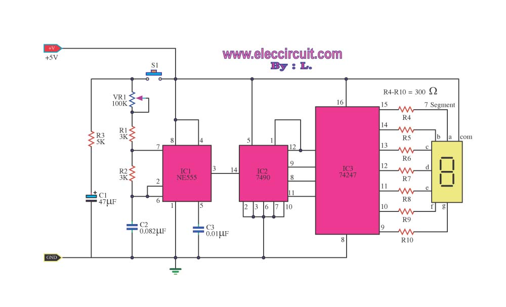
This digital dice circuit is designed to display numbers effectively. When the spin switch is turned off, it converts the input into a binary format using a diode matrix composed of diodes D1 to D9 (1N4148 or 1N914). This...
To measure the input impedance of an unknown circuit, first set the signal generator to a current source with a magnitude of 1 amp. A shunt resistor of 100 megohms is also required. This setup is beneficial for measuring...
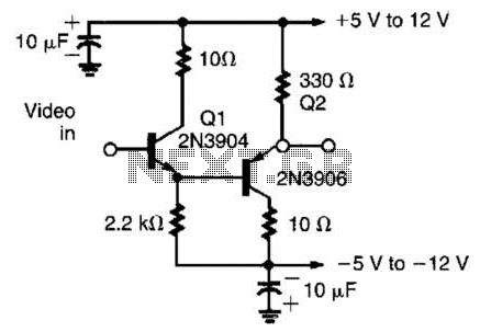
This circuit has demonstrated effectiveness as a video buffer and can easily drive a 75-ohm load to a 1.5-V peak-to-peak output. The bandwidth exceeds 20 MHz, and the DC offset is less than 0.05 V, attributed to the difference...
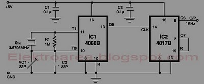
This circuit is designed for accurate time-base generation utilizing the commonly available 3.5795 MHz crystal, which is frequently used in telecommunication equipment. A crystal-based oscillator combined with a divider IC chain or a similar circuit, such as an ASIC,...
Remove the 6 mm screw that secures the lower rear fairing cover. This cover is the black plastic piece to which the spark plug protectors are attached. Only the machine screw should be removed; do not detach the lower...
The most extreme option would be to supply power through a battery pack. A more plausible source would be the car's battery. However, since the objective of the circuit is to activate the buzzer when the headlights are on,...