
field strength meter

The moisture level LED meter circuit typically comprises a few essential components: a moisture sensor, an operational amplifier (op-amp), resistors, a power supply, and LEDs for visual indication. The moisture sensor is the primary component responsible for detecting the moisture content in the material being measured. It usually consists of two conductive probes that are inserted into the medium. When moisture is present, the electrical resistance between the probes decreases, allowing current to flow more easily.
The output from the moisture sensor is fed into an op-amp configured as a comparator. This comparator compares the sensor output to a predefined reference voltage. Depending on the moisture level detected, the op-amp will switch its output state, turning on one or more LEDs to indicate whether the moisture level is above or below a certain threshold. For instance, a green LED may illuminate when the moisture level is adequate, while a red LED may light up when the moisture is too low, signaling the need for watering.
Resistors are used to set the gain of the op-amp and to limit the current flowing through the LEDs, ensuring they operate within their safe limits. The circuit is powered by a DC power supply, which can be a battery or an external power adapter, depending on the application.
This moisture level LED meter circuit is particularly useful for gardeners, farmers, and anyone involved in maintaining plants or monitoring moisture levels in various materials. Its simplicity and effectiveness make it an excellent project for both beginners and experienced electronics enthusiasts.Here is a very simple and useful project of a moisture level LED Meter circuit that can be used as a sensor or detector to measure humidity or moisture level in plants, soil, wood, wall, floor etc.. 🔗 External reference
Related Circuits
The circuit involves the switching of feedback resistors for an operational amplifier (op-amp) that is driven by a Radio Shack 276-115 selenium solar cell, resulting in a multirange linear light meter. A 1000-megohm resistor is utilized for the highest...

The schematic for this tutorial is straightforward. It involves connecting the ADXL320 sensor to the PIC microcontroller and an LED. The power supply is assumed to be a +5V battery to power the PIC. A custom power circuit can...
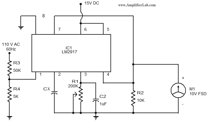
The circuit diagram of a simple capacitance meter is presented here. The primary component of this circuit is the frequency-to-voltage converter. The simple capacitance meter circuit utilizes a frequency-to-voltage converter as its central element to measure capacitance values. This circuit...
A 0 to 2 MHz frequency meter with a Minimum Mass Wireless Coupler, based on the ATMega8. Range to the Minimum Mass Base Unit is 10 to 15 cm. Since the frequency meter is battery operated, it can be...
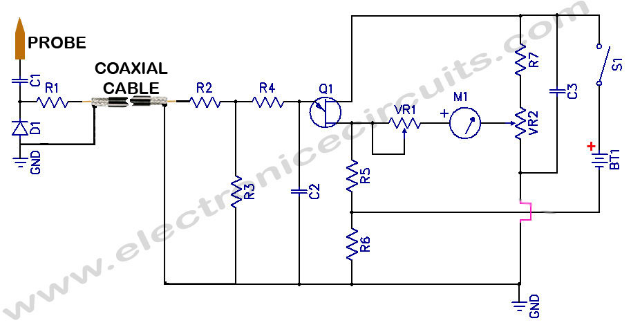
Sensitive RF Voltmeter Probe Circuit. This circuit measures RF voltages beyond 200 MHz and up to approximately 5V. The sensitive RF voltmeter probe circuit is designed to accurately measure radio frequency (RF) voltages in the range exceeding 200 MHz,...
In the circuit below, a quad voltage comparator (LM339) is used as a simple bar graph meter to indicate the charge condition of a 12 volt, lead acid battery. A 5 volt reference voltage is connected to each of...