
Field-strength meter II

The field-strength meter is a simple yet effective device used to measure the strength of electromagnetic fields. The design emphasizes minimalism, relying on a limited number of components to achieve functionality. The core of the circuit typically includes a diode, which rectifies the incoming radio frequency signals, and an analog meter or LED indicator to display the signal strength.
To enhance the range of the field-strength meter, a DC amplifier can be integrated into the circuit. This amplifier will boost the signal received by the antenna, allowing for more accurate readings at greater distances. The amplifier can be configured using operational amplifiers (op-amps) or transistors, depending on the desired specifications and complexity of the design.
The use of a single wire as an antenna is a practical approach in this circuit. This wire acts as a simple monopole antenna, which is effective for receiving radio waves. The length of the wire can be adjusted to optimize the reception for specific frequency ranges.
In summary, the described field-strength meter is a versatile tool for electromagnetic field measurement, with the potential for increased range through the addition of a DC amplifier. The straightforward design and use of a single-wire antenna make it accessible for various applications in electronics and radio frequency testing."Minimum-parts" field-strength meter is shown here. For more distant testing, add the dc amplifier. Use a single wire for antenna.
Related Circuits
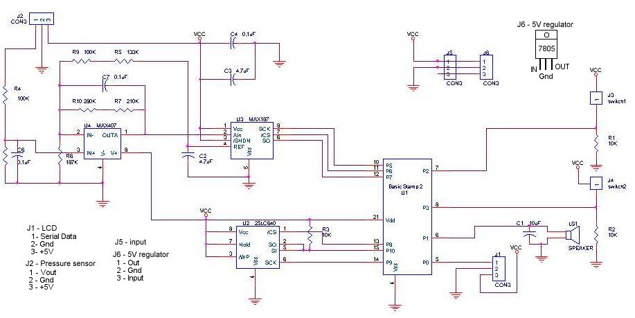
A method for determining altitude involves the use of barometric pressure; however, it presents certain challenges. The relationship between pressure and altitude is not linear but rather complex, a concept developed by the army in the 1930s. The equation...
This meter appears to function well, as demonstrated in a YouTube video about the LM3915 circuit. However, the schematic differs significantly. If the provided schematic is followed, it is uncertain whether everything would operate correctly. A peak detector circuit...
This standalone digital thermometer regulates the temperature of a device based on its requirements. It displays the temperature on four 7-segment displays, with a range from 55 to +125 °C. The core of the circuit is the AT89S52 microcontroller,...
The circuit utilizes two quad voltage comparators (LM339) to illuminate a series of eight LEDs that indicate volume levels. Each of the eight comparators is biased at progressively higher voltages established by a voltage divider, allowing the lower right...
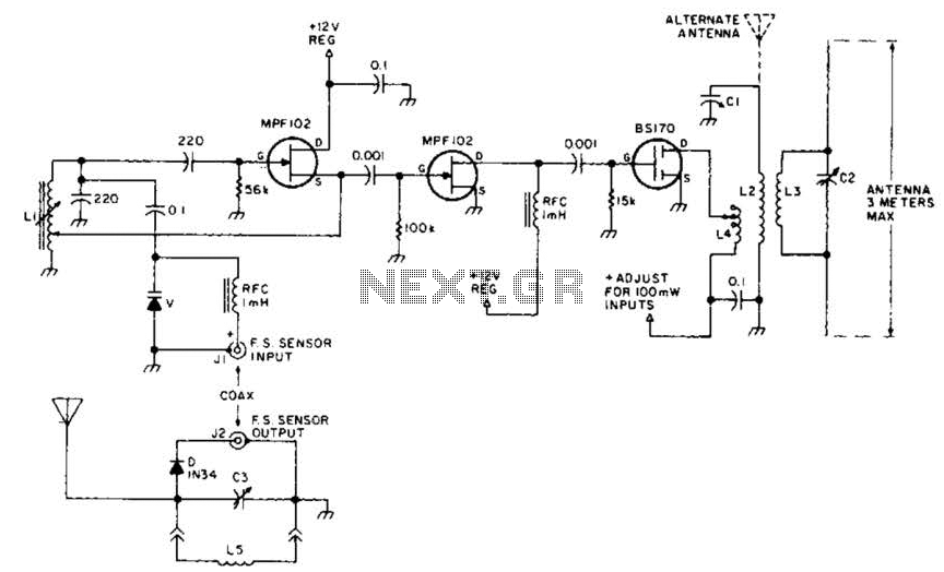
This field strength meter consists of a tuned crystal detector that generates a DC output voltage from a transmitted signal. The DC voltage is utilized to modulate the frequency of a transmitter with a power output of 100 mW,...
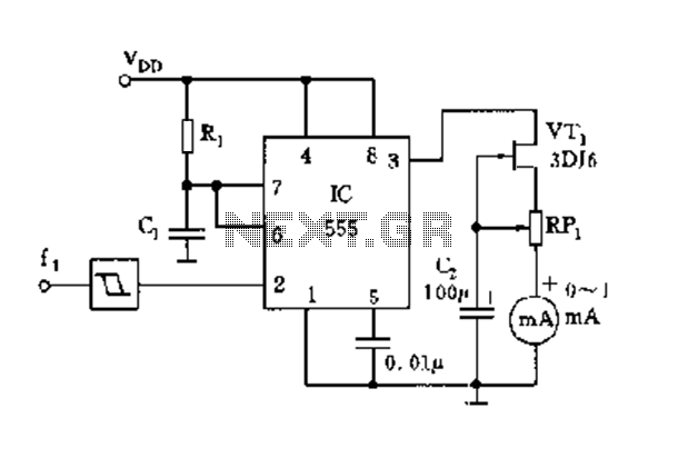
The circuit consists of a 555 timer along with components R1, C1, and other elements configured as a monostable delay circuit. The input square wave signal is shaped by a Schmitt trigger to meet the triggering requirements. The 555 timer...