
LED VU Meter

The circuit design employs the LM339, a quad comparator, which is capable of comparing input voltage levels against predefined reference voltages. The voltage divider configuration is crucial for establishing these reference levels, ensuring that each comparator activates at specific thresholds corresponding to the desired volume levels.
In this setup, the input signal is fed into the non-inverting terminals of the LM339 comparators. The inverting terminals are connected to the voltage divider outputs, which are derived from a stable reference voltage. As the input signal increases, it eventually surpasses the reference voltage set by the first comparator, turning on the first LED. This process continues sequentially, with each comparator turning on its corresponding LED as the input voltage crosses the respective thresholds.
The output of each comparator is connected to the anode of each LED, while the cathodes are grounded. Resistors are placed in series with the LEDs to limit current and prevent damage. The design ensures that the LEDs illuminate progressively, providing a visual representation of the volume level, with the first LED indicating the lowest level and the last LED indicating the highest.
This circuit is particularly useful in audio applications, where visual feedback on volume levels is desired. The use of LM339 comparators allows for precise voltage comparisons, ensuring reliable operation across a range of input conditions. Additionally, the simplicity of the design makes it easy to implement in various electronic projects, providing a straightforward method for volume indication using LED displays.The circuit below uses two quad voltage comparators (LM339) to illuminate a series of 8 LEDs indicating volume level. Each of the 8 comparators is biased at increasing voltages set by the voltage divider so that the lower right LED comes on first when the input is about 400 millivolts or about 22 milliwatts peak in an 8 ohm system
🔗 External reference
Related Circuits
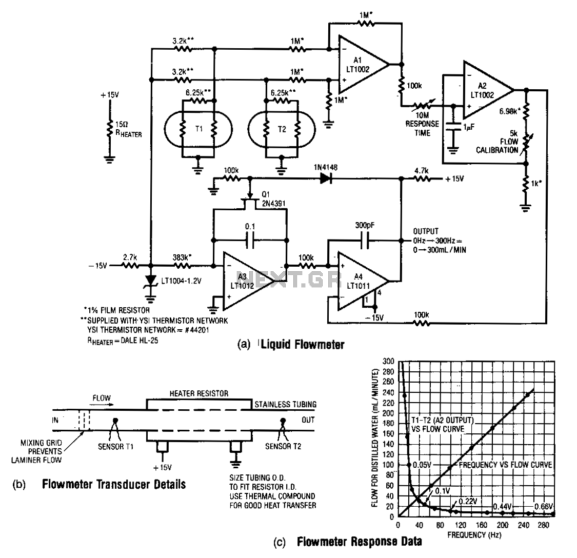
This design measures the differential temperature between two sensors. Sensor T1, located before the heater resistor, measures the fluid's temperature prior to heating by the resistor. Sensor T2 detects the temperature rise induced in the fluid by the resistor's...
The circuit utilizes two white LEDs, with the second LED connected across the emitter of the transistor and the negative ground. It requires its own limiting resistor in series, similar to R15 and D3 in the circuit diagram. If...

U1a serves as an oscillator, while U1b functions as the measurement component of the circuit. It converts an unknown capacitance into a pulse-width modulated signal, similar to the operation of an automotive dwell meter. The meter is linear, meaning...
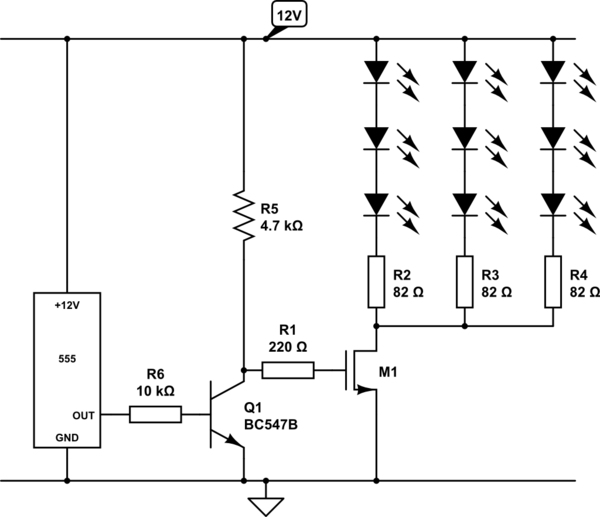
Create a circuit using a 555 timer to operate 72 LEDs simultaneously. A circuit has already been constructed, but there are concerns regarding its safety and longevity. A picture of the circuit is provided for review, and assistance is...
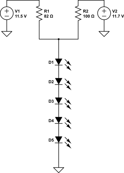
A series of LEDs is intended to display at two brightness levels, and there is uncertainty regarding the proper wiring. This setup is for additional running lights and brake lights on a bicycle. When using the series LED calculator,...
In various industrial processes, it is essential to rotate a DC (or AC) motor both forward and reverse for a specified duration. Initially, the motor rotates forward (clockwise) for a certain period (approximately 2 to 3 minutes), then stops...