
really need help on PWM and PPM circuit

The PWM (Pulse Width Modulation) and PPM (Pulse Position Modulation) circuits are essential in various applications, including motor control, LED dimming, and communication systems. In a PWM circuit, the width of the pulse is varied while maintaining a constant frequency, allowing for control over the power delivered to a load. Conversely, a PPM circuit modulates the position of the pulse within a fixed time frame, which can be particularly useful in remote control systems and data transmission.
To troubleshoot issues with the PWM and PPM circuit, it is crucial to start by examining the circuit design. Key components typically include a microcontroller or timer IC, which generates the desired pulse signals. Additional components may include resistors, capacitors, and possibly MOSFETs or transistors to drive larger loads.
Common problems in PWM and PPM circuits may arise from incorrect timing configurations, inadequate power supply, or improper component values. It is advisable to check the duty cycle settings in the PWM configuration, as this directly affects the output voltage and current supplied to the load. In PPM circuits, ensure that the timing intervals for pulse positioning are accurately set to avoid data corruption or miscommunication.
Using an oscilloscope to visualize the output waveform can provide valuable insights into the operation of the circuit. This will help identify whether the pulse width or position deviates from the expected parameters. Additionally, verifying the connections and ensuring that all components are functioning correctly can resolve many issues.
For further refinement, it may be beneficial to refer to application notes specific to the components used in the circuit or consult relevant datasheets. This can provide additional guidance on the optimal configuration and troubleshooting techniques for PWM and PPM applications.hello everyone..im need some helps i`ve construct the PWM and PPM circuit the output going smoothly but i`ve some problem im not very.. 🔗 External reference
Related Circuits

Joule thief circuit along with videos, circuit diagrams, and explanations. The Joule thief circuit is a minimalist boost converter designed to extract energy from low-voltage sources, such as depleted batteries. This circuit is particularly effective for powering small electronic...
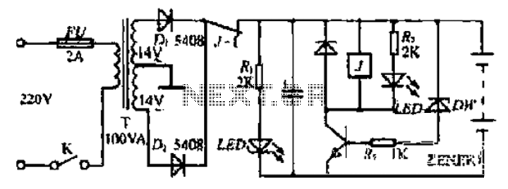
Various values of D3 can be utilized to achieve different output voltages ranging from approximately 0.6V to around 30V. It is important to note that at elevated voltages, the circuit's performance may diminish, potentially resulting in lower current output....
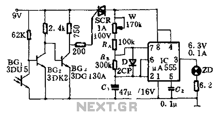
This circuit is designed for nighttime illumination and corridor lighting. During daylight, sufficient light causes BG3 to conduct, preventing the SCR from oscillating. As a result, the circuit remains inactive, and the light does not turn on. At night,...
Bidirectional control is implemented for a motor to increase its operational degree. The motor can rotate in either direction with a current of 1A. A variable duty cycle multivibrator is utilized to achieve the construction and control of the...
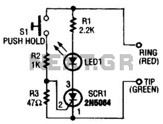
Section Ul-a is configured as a high-gain inverting voltage amplifier that is inductively coupled to the phone line via LI. Inductor LI is a homemade unit that consists of 250 turns of fine, enamel-coated wire that is wound on...
CMOS interface circuit with PMOS cross-coupled PMOS integrated circuit featuring high input impedance, where the input current can be ignored. The CMOS and PMOS interface circuit is illustrated in the accompanying figure. The CMOS interface circuit utilizing PMOS cross-coupled configurations...