
Fixed Voltage Power Supply

A fixed voltage power supply typically consists of a transformer, a rectifier, a filter capacitor, and a voltage regulator. The transformer steps down the AC mains voltage to a lower AC voltage suitable for the desired output. The choice of transformer is critical, as it determines the output voltage and current capabilities.
The rectifier, often implemented using a bridge configuration with diodes, converts the AC voltage from the transformer into pulsating DC voltage. This pulsating DC is not suitable for most applications, so a filter capacitor is used to smooth the output voltage. The capacitor charges and discharges to reduce voltage ripple, providing a more stable DC voltage output.
The voltage regulator is responsible for maintaining a constant output voltage despite variations in load current or input voltage. Common types of voltage regulators for fixed voltage applications include linear regulators, such as the 78xx series, and low-dropout (LDO) regulators. The selection of the regulator will depend on the desired output voltage, current rating, and efficiency requirements.
In this design, the maximum output current is specified as 1.5A. This indicates that the components, particularly the transformer and regulator, must be rated to handle this current without overheating or failing. Proper heat dissipation measures, such as heat sinks, may be necessary for the voltage regulator to ensure reliable operation.
Overall, the fixed voltage power supply is an essential component in many electronic devices, providing a stable and reliable power source for various applications.The fixed voltage power supply is useful in applications where an adjustable output is not required. This supply is simple, but very flexable as the voltage it outputs is dependant only on the regulator and transformer you choose. The maximum output current is 1.5A. 🔗 External reference
Related Circuits
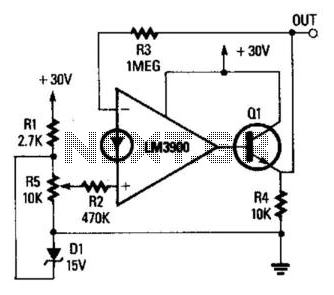
The operational amplifier (op amp) is configured as a non-inverting DC amplifier with a gain determined by the ratio of resistors R3 and R2. The input voltage to the op amp can vary between 0 and 15 V through...
This circuit is so sensitive it will detect mains hum. Simply move it across any wall and it will detect where the mains cable is located. It has a gain of about 200 x 200 x 200 = 6,000,000...
The range of this FM transmitter is approximately 100 meters when powered by a 9V DC supply. The circuit consists of three stages. The first stage is a microphone preamplifier. The FM transmitter circuit is designed to convert audio signals...

This circuit utilizes a single junction component, either one LM393 dual comparator or one LM339 quad comparator. Resistors RV1 and RV3 are responsible for establishing the full-scale reference voltage, while resistors RV2 and RV4 are used to set the...
The foundation of this amplifier is detailed in Project 03, which does not claim to be cutting-edge; the base design is over 20 years old. It is straightforward to assemble, utilizes readily available components, and is stable and dependable....
The following diagram represents a 20W power amplifier circuit constructed using the EL34 tube component. The EL34 is a well-known tube that is highly regarded for use in power tube amplifiers. The circuit includes both the tube amplifier schematic...