
20W Power Tube Amplifier with EL34

The power amplifier circuit is designed around the EL34 vacuum tube, which is known for its high performance in audio amplification applications. The circuit typically operates at a plate voltage ranging from 250V to 400V, which is suitable for achieving the desired output power of 20W. The EL34 tube is a pentode that provides excellent linearity and low distortion, making it ideal for high-fidelity audio applications.
The schematic includes a detailed component list, which specifies the values and types of resistors (R1-R21) and capacitors (C8-C14) used in the design. For instance, R1 is a 470K ohm resistor rated at 0.5W, while C8 and C9 are 0.1uF capacitors rated at 630V. The power supply section is crucial, as it must provide stable voltage and current to the amplifier circuit. The use of a high-voltage power supply is necessary to ensure that the EL34 operates within its optimal range.
For stereo applications, two identical EL34 amplifier circuits can be constructed and connected in parallel, ensuring that each channel receives the same power supply. This configuration allows for enhanced audio performance and improved channel separation, which is critical in stereo sound reproduction.
The design draws inspiration from vintage audio equipment, particularly the output section of late 1940s AM radios, which utilized similar tube configurations. The overall output of this amplifier is 4 Watts per channel, providing a balanced and rich sound experience when used with compatible speakers.
In summary, this 20W power amplifier circuit utilizing the EL34 tube is a classic design that combines vintage aesthetics with modern performance requirements, suitable for audio enthusiasts and professionals alike.The following diagram is the circuit diagram of 20W power amplifier which build based tube component EL34. EL34 is very famous tube and great for power tube amplifier. The circuit above is complete circuit contains tube amplifier circuit diagram and power supply circuit diagram.
To make the stereo channel amplifier, build the similar amplifier c ircuit only and connect to the power supply using parallel connection with another same amplifier. Tags: 20w EL34 amplifier, 20w tube amplifier, el34 amplifier, el34 circuit, el34 power amplifier, el34 schematic, el34 tube amplifier, el34 wiring, power tube amplifier el34, 35W Tube Power Amplifier with EL34. This tube amplifier designed in 1953 and worked from 1954 until 1989. Schematic Diagram: Power Supply: Component List: R1=470K 0, 5W R13-21=820K 0. 5W C8-9=0. 1uF 630V R2-5= 2K2 0. 5W R14-22=5K6 0. 5W C10-14=0. 47uF 630V R3=150K 0. 5W R15-20= 680K 0. 5W C11-13=25uF 40V R4= 220K 0. 5W R16-19=100K 0. 5W V1= E80CC R6-10= 56K 0. 5W R17-18=3K3. This is the circuit diagram of stereo tube amplifier using 6SQ7-GT and 6V6-GT. The tube amplifier circuit is uses the total of 5 power vacuum tube. The diagram is based on the output section design of typical late 1940`s old AM Trutone radio with 6 tubes.
The output will be 4 Watts per channel (2x4W. 🔗 External reference
Related Circuits
This circuit illustrates a 2W RF amplifier based on the M/A-Com LF2810A MOSFET. The transistor is rated for 10 watts at 28 volts. The 2W RF amplifier circuit utilizing the M/A-Com LF2810A MOSFET is designed to amplify radio frequency signals...
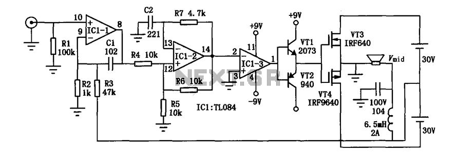
A conventional digital home theater amplifier necessitates a dedicated integrated circuit, which is often produced by a limited number of manufacturers, resulting in higher costs. This circuit element can be produced using standard components, delivering a power output of...
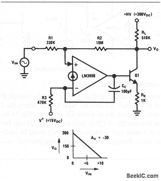
This circuit is an inverting amplifier with an output voltage swing from approximately 0 to +300 V. Any transistor can be utilized for Q1, as long as the breakdown voltage exceeds 300 V (since the full high voltage will...
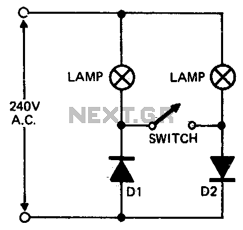
When setting up photographic floodlamps, it is sometimes desirable to operate the lamps at lower power levels until actually ready to take the photograph. The circuit allows the lamps to operate on half-cycle power when the switch is open...
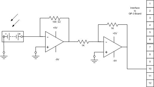
The solar cell used for the solar tracking experiment is made from crystalline silicon, with a maximum voltage rating of 55V and a maximum current rating of 300 mA. It can be purchased at local Radio Shack stores for...
A real-size printout of the PCB is created to verify the dimensions of all components against it. If a component is too large or small to fit its PCB pads, adjustments to the PCB layout can be made, or...