
Voltage Sensitive Probe

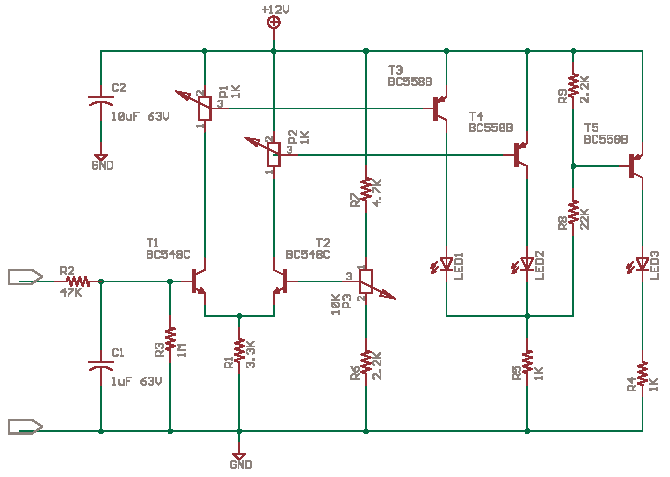
This circuit operates on the principle of detecting electromagnetic fields generated by alternating current (AC) sources, specifically the 50/60 Hz mains hum. The circuit's high sensitivity allows it to respond to low-level signals that are typically produced by electrical wiring within walls. The gain of 6,000,000 is achieved through a series of amplifying stages, which may include operational amplifiers configured in a non-inverting mode to maximize the output signal relative to the input.
The input stage of the circuit is designed to have very high impedance, which is crucial for minimizing loading effects on the detected signals. This high impedance input is typically implemented using field-effect transistors (FETs) or high-impedance operational amplifiers, which ensure that the circuit does not draw significant current from the source being measured, thereby preserving the integrity of the detected signal.
In addition to detecting mains hum, the circuit is capable of sensing static electricity and the proximity of objects, such as a human hand, through capacitive coupling. This is facilitated by the circuit's ability to detect changes in the electric field in its vicinity. When a hand approaches the sensor, the capacitance between the sensor and the hand alters, resulting in a measurable change in voltage at the input.
To further enhance the circuit's functionality, it may include a filter section to eliminate unwanted noise and improve the signal-to-noise ratio, allowing for clearer detection of the desired signals. The output can be connected to an LED indicator or an audio output device, providing a visual or auditory signal when the presence of mains hum or static electricity is detected.
Overall, this highly sensitive circuit exemplifies the ability to detect subtle electromagnetic phenomena, making it a valuable tool for various applications in electrical diagnostics and safety assessments.This circuit is so sensitive it will detect "mains hum." Simply move it across any wall and it will detect where the mains cable is located. It has a gain of about 200 x 200 x 200 = 6,000,000 and will also detect static electricity and the presence of your hand without any direct contact.
You will be amazed what it detects! There is static electricity EVERYWHERE! The input of this circuit is classified as very high impedance. 🔗 External reference
Related Circuits

This is a schematic diagram of a micropower voltage-controlled oscillator circuit. This circuit can generate square and triangle wave outputs and only requires minimal power. The micropower voltage-controlled oscillator (VCO) circuit is designed to produce both square and triangle waveforms,...
The circuit possesses significant educational value. It has not been tested. Users can simulate and test it or construct it to evaluate its performance. The circuit functions as a simple analog-to-digital converter. Optocouplers can be used in place of...
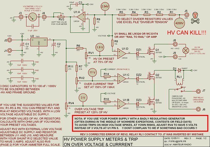
High voltage resistors for the high voltage divider are SFERNICE or PHILIPS type VR37 (3.5 kV - 0.4 W). They are not expensive (even if they are sold in quantities of 25 or 50 units), and it is always...

This circuit offers a distinctive solution to a prevalent power distribution issue at the system level. When the supply voltage to a remote board must travel through a lengthy cable, the voltage at the termination point may decrease to...
The current source IC Type LM334 is utilized in this specialized application, which features a minimal temperature coefficient and operates with a very low current draw of only 10 µA at room temperature. This current increases slightly with higher...
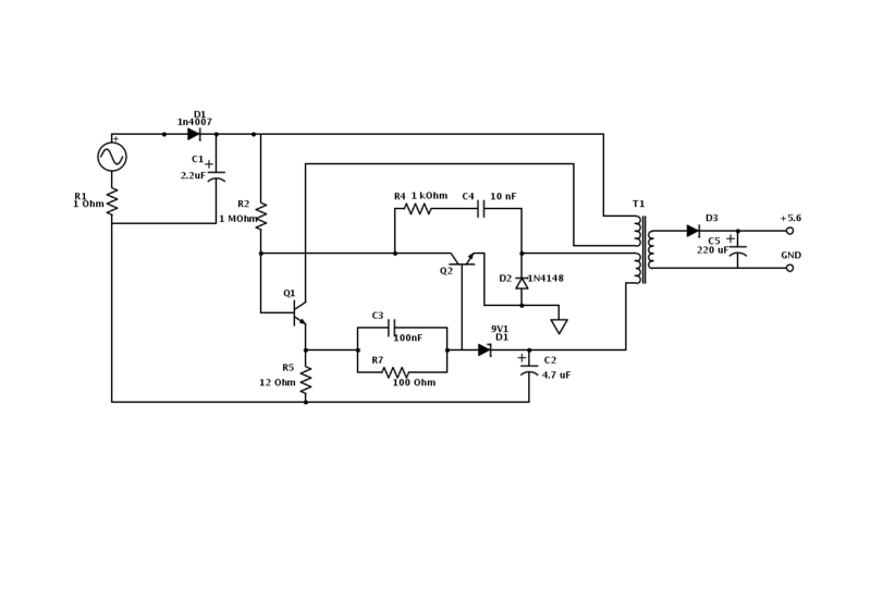
An old Nokia phone charger with a 5.6 V output was modified to provide 12 V by changing the Zener diode from a 9.1 V to a 16 V component. The circuit is mostly understood, but clarification is needed...