
Inductance Meter Circuit

The inductance meter adapter circuit is designed to enhance the functionality of a standard digital voltmeter, allowing for precise measurement of inductance values essential for various electronic applications. The circuit typically includes a few key components: resistors, capacitors, and a range switch. The resistors are used to set the voltage levels for the low and high ranges, while capacitors may be employed to filter out noise and stabilize the readings.
The schematic diagram is crucial for understanding the interconnections between these components. The circuit may feature a microcontroller or an operational amplifier to process the signals from the inductors being measured. This processing allows for accurate conversion of inductance to a corresponding voltage that can be read by the digital voltmeter.
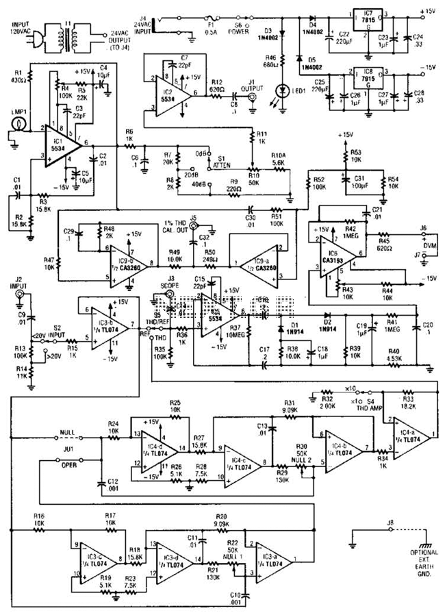
In practical applications, the inductance meter adapter is invaluable for engineers and hobbyists alike when working with inductors in power supply designs or other electronic circuits. The ability to easily switch between measurement ranges allows for flexibility in testing various inductance values, ensuring that designers can optimize their circuits effectively. The calibration process is straightforward, requiring minimal equipment and ensuring that the measurements are reliable and accurate, which is critical in electronic design and troubleshooting.This inductance meter is actually an adapter to your digital voltmeter (DVM). Using this circuit now your voltmeter is capable of measuring inductor value. Inductance meter is very helpful in designing switch mode power supply, since its often needed to wind the coil by hand and measure the inductance fro trial and error to get the required value. Here is the schematic diagram of the inductance meter adapter circuit: This circuit is designed to provide twi measurement range. The low range will measure inductors with inductance value between 3uH to 500uH, and the high range will measure inductance values between 100uH and 5mH.
To calibrate this inductance meter adapter, connect a digital voltmeter, swith the voltmeter to 200 mV range, short the test probe and adjust the zero (R1) to give zero millivolt reading on your digital voltmeter. To calibrate the low range of this inductance meter adapter, switch the voltmeter to low range position, and select 2 V range for the digital voltmeter.
Test a known inductor that has value around 400uH, adjust the low calibration pot to give correct reading of 1mV / uH. If you use a 400uH inductor then you must adjust the calibration to give exactly a 400mV reading. For high range calibration, switch the range selector to high position and use a known inductor around 5 mH, adjust the high calibration pot to give 100mV per mH.
A 5 mH inductor should give a 500mV reading on your DVM. [Source: Marc Spiwak] 🔗 External reference
Related Circuits
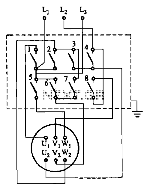
The circuit illustrated in Figure 3-36 includes the starter contact closure detailed in Table 3-1. In the figure, U1, V1, W1, and U2, V2, W2 represent the first three-phase stator windings of the motor terminals. The circuit depicted in Figure...

This circuit is a graphic equalizer that can be built with a low component count and is controlled using the LA3600 single IC chip. The internal design of the chip utilizes a transistor gyrator circuit, with connections to external...
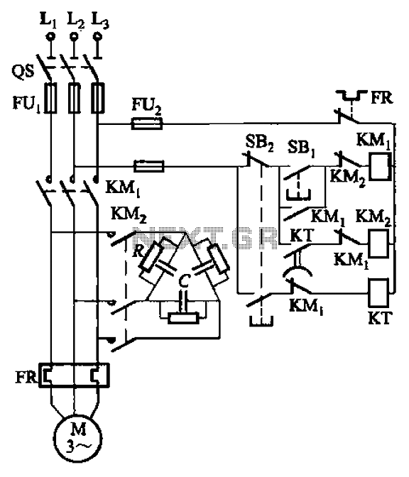
The circuit illustrated in Figure 3-151 consists of capacitor banks arranged in a specific configuration. Figure 3-151 (a) depicts capacitor banks connected in a shaped manner, which is suitable for use with shaped or Y-connected motors. Figure 3-151 (b)...
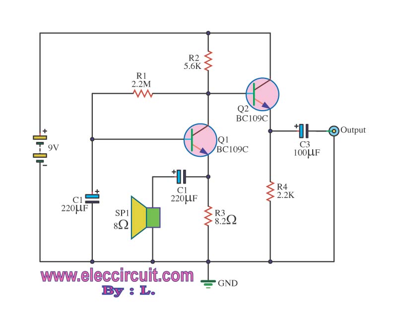
This may appear to be a basic inquiry, but the individual is a beginner in electronics. A preamplifier has been constructed to amplify the signal from a small speaker that is utilized. The preamplifier circuit is designed to increase the...
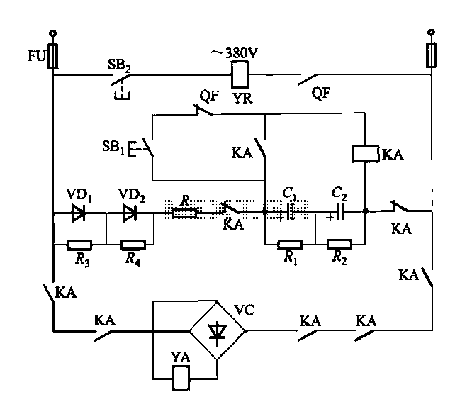
The DW15-200-630A breaker solenoid is a DC solenoid designed for short-time operation. The DK-1 control box utilizes an AC power switch to manage the electromagnet circuit, as depicted in Figure 6-7. The DK-1 type electromagnetic control box includes several...
The circuit comprises a low-distortion, 1-kHz oscillator designed to measure Total Harmonic Distortion (THD) at a user-selected voltage level, suitable for voltage amplifiers or for testing amplifiers with power levels up to 600 W. It is capable of detecting...