
Flashing Brake Light for Motorcycles Circuit

The flashing brake light circuit operates by utilizing a combination of inverters and a timing mechanism to create a visual alert for vehicles behind a motorcycle. Upon activation of the brake light switch S1, a voltage is applied to the circuit, energizing the components U1 and U2. U1 typically functions as a power supply or a control unit, while U2 consists of two inverters that play a crucial role in generating the flashing effect.
The inverters in U2 are configured in such a way to produce a square wave output, which alternates the state of the brake light between on and off. This flashing pattern not only enhances visibility but also draws attention to the motorcycle, thereby improving safety during braking situations.
Key components of the circuit may include resistors and capacitors that determine the frequency of the flashing light. The values of these passive components can be adjusted to achieve the desired flash rate, allowing for customization based on user preference or regulatory requirements.
Additionally, the circuit may incorporate a diode to prevent back EMF from affecting the operation of the inverters, ensuring reliable performance. Proper layout and grounding techniques are essential to minimize noise and interference, which could disrupt the flashing function.
Overall, this circuit design is a straightforward yet effective solution for enhancing the visibility of motorcycle brake lights, contributing to safer riding conditions.This flashing brake light circuit can be used for motorcycles. When brake-light switch S1 is closed, power is applied to U1 and U2. Two inverters of U2, a.. 🔗 External reference
Related Circuits
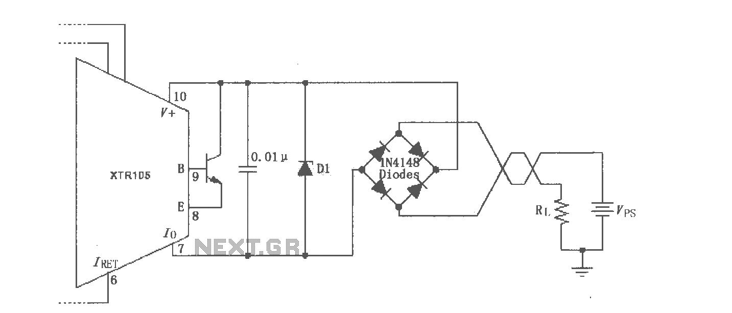
The XTR105 reverse voltage and over-voltage surge protection circuit is illustrated. A Zener diode rated at 36V can be utilized, with options including 1N4753A or 1N6286A. The maximum supply voltage (Vps) should be less than the minimum breakdown voltage...
This project involves a straightforward and practical 12V power supply circuit utilizing the LM7812 integrated circuit (IC). The LM7812 is a three-terminal fixed voltage regulator IC housed in a TO-220 package. It incorporates several built-in features such as thermal...
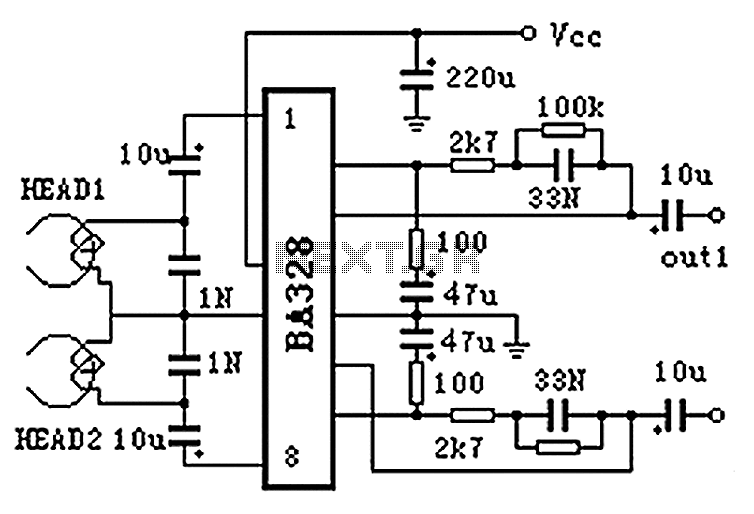
The BA328 is a dual preamplifier circuit designed with minimal external components, facilitating straightforward installation within a single 8-pin DIP package. The circuit features a wide operating voltage range, low noise levels, and high open-loop gain, ensuring good balance...

Figure 1 illustrates a circuit diagram related to an audio circuit that incorporates a resistance between two leads connected to a rain alarm probe. Figure 2 demonstrates the connection of a capacitor to the probe within the audio circuit....
This circuit gives a low-level output when sufficient lighting is present, functioning as a light detector. It can issue a command to turn on lights when darkness falls. Its output is compatible with TTL levels, providing a low logic...
The clock is based on the PIC16F877 microcontroller from Microchip Technology Inc., which performs all of the logic necessary to decode the MSF signal and display the time on twelve 7-segment displays. The circuit design incorporates the PIC16F877 microcontroller, a...