
Flashing LED Circuit

The circuit consists of two NPN transistors, which function as switches to control the LEDs. The transistors are connected in a way that allows them to alternately turn on and off, creating a flashing effect for the LEDs. The basic operation relies on the charging and discharging of a capacitor, which is connected in the feedback loop of the circuit.
When power is applied, one of the transistors will initially turn on, allowing current to flow through its collector-emitter path. This action will also charge the capacitor. As the capacitor charges, the voltage across it increases until it reaches the base-emitter threshold voltage of the second transistor. At this point, the second transistor will turn on, causing it to conduct and turn on the second LED.
Simultaneously, the first transistor will begin to turn off as the capacitor discharges, which will eventually lead to the first LED turning off. The cycle continues as the capacitor charges and discharges, resulting in a flashing effect of the two LEDs.
Resistors are typically included in the circuit to limit the base current to the transistors and to protect the LEDs from excessive current. The values of these resistors, along with the capacitor, can be adjusted to change the flashing rate of the LEDs. This circuit serves as an excellent demonstration of basic electronic principles, including the operation of transistors, capacitors, and the use of feedback in oscillating circuits.This is a simple flashing led circuit with 2 leds and 2 NPN transistors. It illustrates the behavior of transistors and capacitors and if you use an oscill.. 🔗 External reference
Related Circuits

An operational amplifier along with transistors Q1 and Q2 forms an exponential converter to produce an exponential gain control current, which is fed into the rectifier. A reference current of 150 pA, with a voltage of 15 V and...

This simple circuit can be used to charge a pair of AA or AAA-sized cells using solar energy. It has been utilized to maintain the operation of devices such as a Palm Pilot and a Walkman radio continuously. This...

The adjustment potentiometer RP can modify the magnitude of the DC output voltage. The adjustment potentiometer, designated as RP, is an essential component in various electronic circuits, particularly in power supply systems and signal conditioning applications. It serves as a...
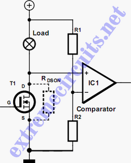
In applications where a MOSFET is used to switch a load, it is relatively straightforward to incorporate short-circuit or overload protection. This can be achieved by utilizing the internal resistance RDS(ON), which generates a voltage drop proportional to the...

The circuit schematic is straightforward. Information regarding the assembly and testing of circuits is not provided, as there are many instructional resources available. The circuit schematic in question is designed to be simple and user-friendly, allowing for ease of understanding...

Figure (a) illustrates an infrared emission circuit composed of a 12-key keyboard and an S2559. Figure (b) displays a DTMF decoder circuit along with a channel control circuit utilizing the MT8870. Figure (c) presents a voltage amplifier circuit constructed...