
Three motor control circuit start and stop sequence requirements

The circuit utilizes a sequential control mechanism to manage the operation of multiple motors. Motor M1 acts as the primary motor, and its activation is critical for the operation of motors M2 and M3. This configuration ensures that the motors are interdependent, where the starting of M2 and M3 is contingent upon the operational status of M1.
The shutdown sequence is designed to prioritize the stopping of motor Mz, which can be halted independently of the other motors. This feature provides flexibility in controlling the system, allowing for maintenance or safety protocols to be enacted without affecting the entire circuit.
The inclusion of switch SB2 serves as a manual control point for stopping motor M1. When SB2 is activated, it triggers a response that leads to the immediate shutdown of motors M2 and M3, thereby ensuring that all motors are synchronized in their operation and shutdown processes.
This design is particularly useful in applications where motors are part of a larger system, such as in conveyor belts or assembly lines, where the coordinated operation of multiple motors is essential for efficiency and safety. The circuit can be further enhanced with additional features such as overload protection, thermal sensors, or automated control systems for improved performance and reliability. Circuit shown in Figure 3-89. After starting the motor Mi can guarantee, it allowed the other two to start the motor. Shutdown, power motivation Mz, can first stop, but as long as the motor M1 stop (press SB2), the motor M2, M3 also stop.
Related Circuits
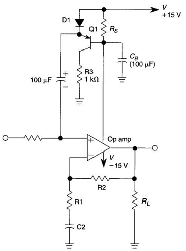
This circuit is an Automatic Gain Control (AGC) system designed for audio-frequency signals. AGC systems typically consist of three main components: an amplifier, a rectifier, and a controlled impedance. In this particular circuit, the functions of both the amplifier...

Automatic electronic refrigerator deodorant sterilization circuit The automatic electronic refrigerator deodorant sterilization circuit is designed to eliminate odors and sterilize the interior of a refrigerator. This circuit typically employs a combination of sensors, microcontrollers, and sterilization techniques to achieve effective...
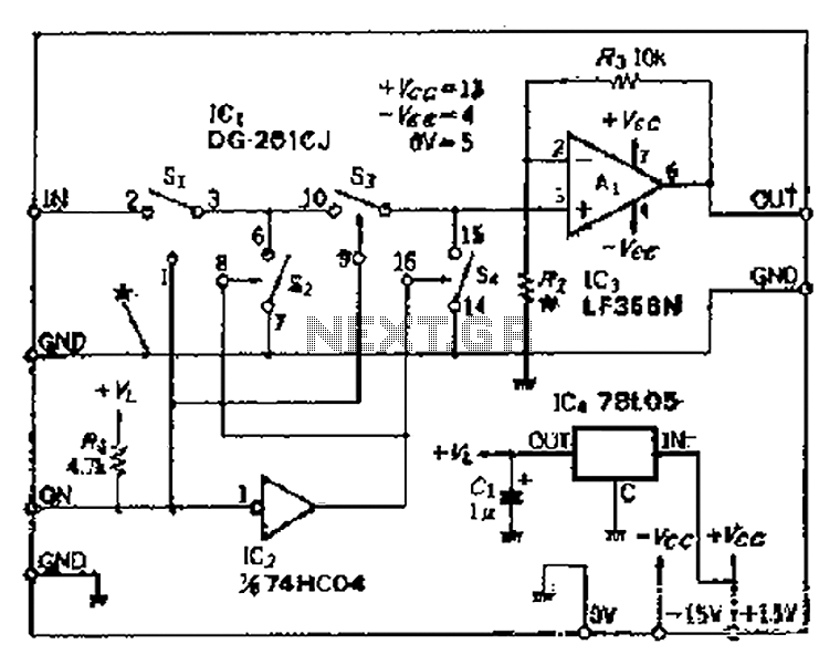
Analog switches SL and SA disconnect the inverted logic signal to terminal 2. S1 and S4 are turned on, allowing capacitance between S1 and S8 to couple. S2 and S4 shunt with an on-state resistance ranging from 50 to...

The DPT Transmitter is a dual-powered voice transmitter designed to operate in two modes: a high-power mode for long-range transmission and a low-power mode for extended battery life. It functions at a low power level of 100 mW and...

The schematic for the board is illustrated below. The three primary components of the board include (1) the power input and voltage regulation, (2) the L297 input and outputs, and (3) the L298 stepper motor control circuit. The motor...
The high durability of a light-emitting diode (LED) makes it suitable for ON/OFF indicator applications. However, there are limitations regarding low operating voltage. Light-emitting diodes (LEDs) are semiconductor devices that emit light when an electric current passes through them. Their...