
Flyback Converters for Dummies
The NIXIE clock design utilizes an AC adapter to eliminate the bulkiness of a traditional mains transformer, instead relying on a boost converter or a flyback converter to achieve the necessary high voltage for the NIXIE tubes. The boost converter is a type of DC-DC converter that steps up the input voltage to a higher output voltage, while the flyback converter is a more efficient option that utilizes a transformer to isolate the input and output, providing the required high voltage with better efficiency.
In the context of the circuit operation, the inductor plays a crucial role in energy storage and transfer. When the battery is connected, the inductor initially resists the change in current due to its inductance, leading to a gradual increase in current. This behavior is a fundamental principle of inductors, characterized by their ability to store energy in a magnetic field. The energy stored in the inductor can be released back into the circuit when the current path is interrupted, allowing for the generation of high voltages necessary for the NIXIE tubes.
The discussion of ferrites emphasizes their importance in enhancing the performance of inductors. By increasing the magnetic flux through the inductor, ferrites enable smaller and more efficient designs, which are particularly beneficial in compact electronic applications like the NIXIE clock. The presence of an air gap in ferrite cores is a critical design consideration, allowing for higher current handling without reaching saturation too quickly, thus optimizing the inductor's performance in power conversion applications.
Overall, the integration of these components and principles creates a sophisticated yet practical high voltage power supply solution for NIXIE tube displays, demonstrating the effective application of inductive principles in modern electronic design.In the NIXIE clocks that I have built, I did not want to have the big and ugly mains transformer in the actual clock itself. Instead I use an AC adapter that fits into the mains wall plug. This means that I have to use some sort of an up-converter to generate the 180V anode supply for the NIXIEs.
This page describes a simple boost converter and amore efficient flyback converter both of which can be used as a high voltage power supply for a 6 NIXIE tube display. Frans Schoofs beautifully explained to me the working of the flyback converter and much of what he explained to me you find reflected on this page. I additionally explain the essentials of inductors and transformers that you need to know. This is just a practical guide to get you going, it is not a scientific treatise on the topic. Consider the simple circuit consisting of a battery connected to an inductor with inductance L and resistance R (Fig.
1). When the battery is connected to the inductor, the current does not immediately change from zero to its maximum value V/R. The law of electromagnetic induction, Faraday`s law prevents this. What happens instead is the following. As the current increases with time, the magnetic flux through this loop proportional to this current increases.
The increasing flux induces an e. m. f. in the circuit that opposes the change in magnetic flux. By Lenz`s law, the induced electric field in the loop must therefore be opposite to the direction of the current. As the magnitude of the current increases, the rate of the increase lessens and hence the induced e. m. f. decreases. This opposing e. m. f. results in a linear increase in current at a rate I=(V/L)*t. The increase in current will finally stop when it becomes limited through the series resistance of the inductor.
At that moment the amount of magnetic energy stored in the inductor amounts to E=0. 5*L*I*I. In words: the inductor does not allow for any abrupt changes in the current. When a change in applied voltage occurs, the inductor will always generate an e. m. f. that counteracts this change. When the circuit is interrupted for instance, the inductor will still try to maintain the current flowing by generating a very high voltage over its terminals. Usually this will result in a spark in which the magnetic energy stored in the inductor is released. This particular behavior of inductors is used in boost converters to boost the voltage to levels above the battery voltage.
Materials like ferrites can be used to increase the magnetic flux in an inductor. When a magnetic field is applied to a ferrite the small magnetic domains in the ferrite will align with this field and increase its magnitude. In this way inductors can be made smaller and with lesser turns and thus with smaller series resistances (smaller losses).
Note that the flipping of these domains costs some energy, but in good ferrites this can be very small. With increasing magnetic flux more and more magnetic domains point into the direction of the field. At a certain point all the magnetic domains point into the direction of the field and at that point we say that the ferrite saturates.
Any further increase in current will only result in a small increase of flux, basically as if the ferrite was not present. Since most ferrites have a very high permeability, already small currents can result in a high magnetic flux.
As a result the ferrite will saturate at a current which is not practical for power conversion applications Ferrite cores for inductors and transformers for power applications therefore have an air gap. An air gap reduces the effective permeability and thus the magnetic flux. The larger the air gap, the stronger the reduction in flux an the higher the maximum current the inductor can handle.
We say that the magnetic energy is stored in the air gap. The photograph shows several inductors for DC/DC converters salvaged from old PCBs from PCs, Laptops 🔗 External reference
Related Circuits
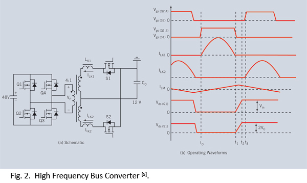
Distributed power systems are commonly used in telecommunications, networking, and high-end server applications, utilizing a 48 V bus voltage derived from the telecom industry. This 48 V bus supplies several isolated point-of-load (POL) converters that power the end loads,...
This type of converter is used to convert analog voltage to its corresponding digital output. The function of the analog-to-digital converter is exactly opposite to that of a digital-to-analog converter. Like a digital-to-analog converter, an analog-to-digital converter is also...
Cost, size, resistance, and current capability drive the choice of inductor for most step-down DC-DC switching converters. Inductors play a crucial role in the operation of step-down DC-DC switching converters, influencing performance parameters such as efficiency, output voltage stability, and...
The LT3465/LT3465A are step-up DC/DC converters designed to drive up to six LEDs in series from a Li-Ion cell. Series connection of the LEDs provides identical LED currents and eliminates the need for ballast resistors. These devices integrate the...
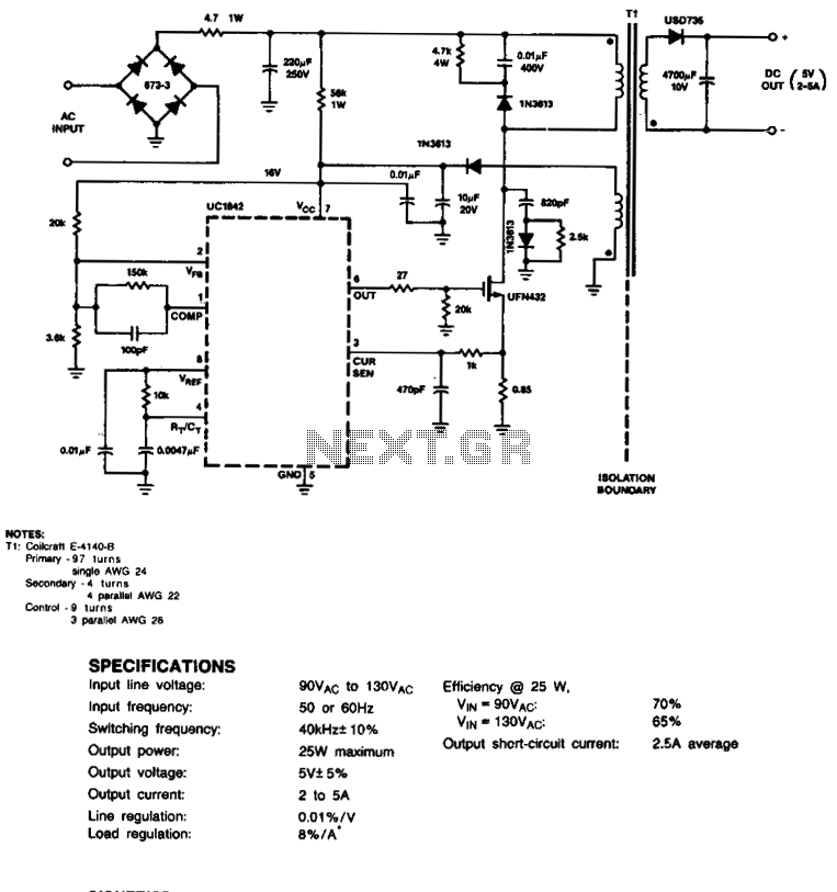
This circuit employs a cost-effective feedback scheme where the direct current voltage generated from the primary-side control winding is monitored by the UC1842 error amplifier. Consequently, load regulation is influenced by the coupling between the secondary and control windings,...

An efficient flyback driver for modern cylindrical rectified television flybacks. Many sources do not provide circuits for driving these transformers, often deeming them ineffective. However, this circuit has been successfully constructed. Significant effort was dedicated to determining the resonant...
Warning: include(partials/cookie-banner.php): Failed to open stream: Permission denied in /var/www/html/nextgr/view-circuit.php on line 713
Warning: include(): Failed opening 'partials/cookie-banner.php' for inclusion (include_path='.:/usr/share/php') in /var/www/html/nextgr/view-circuit.php on line 713