
FM antenna amplifier circuit

The FM antenna amplifier circuit is engineered to enhance signal strength for FM radio stations, particularly in areas with weak reception. The primary components of this circuit typically include a low-noise amplifier (LNA), an antenna input, a power supply, and output connections for the FM tuner.
The circuit operates by receiving the weak radio frequency (RF) signals from the antenna and amplifying them to a level suitable for processing by the FM tuner. The LNA is crucial in this configuration, as it minimizes noise while boosting the signal, ensuring that the quality of the audio output is preserved.
Powering the circuit generally requires a stable DC voltage, often supplied by a battery or an external power adapter. The design may also include filtering components to eliminate unwanted frequencies and ensure that only the desired FM signals are amplified.
The output of the amplifier connects directly to the FM tuner, allowing for improved sound quality and clarity. Proper grounding and shielding techniques should be implemented to prevent interference from other electronic devices.
Overall, this FM antenna amplifier circuit is an effective solution for enhancing FM reception, making it a valuable addition for users experiencing signal issues in their area.Use this fm antenna amplifier in areas where the signal reception of FM stations is too bad. This circuit is just the right thing to do it. It is designed. 🔗 External reference
Related Circuits
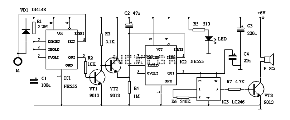
This circuit describes a door alarm system equipped with a time recognition feature. When the owner opens the door, it remains in a normal state for approximately 30 seconds without triggering the alarm. However, if the door is opened...
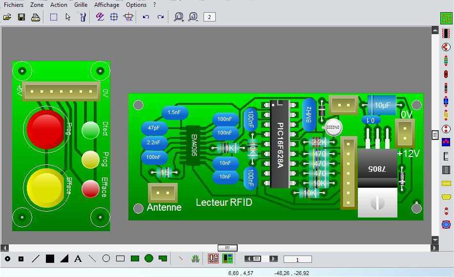
WinCircuit is a software of realization of drawing of printed circuit in single or double layers. Principal qualities are the facility of use and the sight in pseudo 3D which gets a vision of the circuit close to reality....
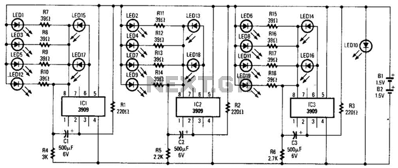
Three individual flashing circuits utilizing an LM3909 LED flasher/oscillator IC create the illusion of a pseudo-random firing order. The capacitors CX1, CX2, and CX3 control the blink rate, which ranges from 0.3 to 0.8 seconds. The wide tolerance range...
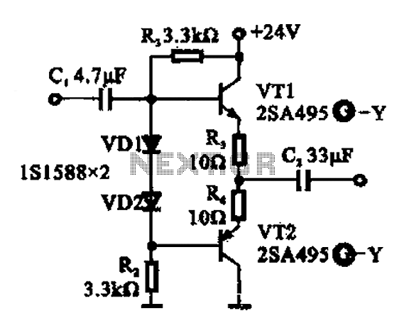
A buffer amplifier is utilized as a transistor emitter follower buffer amplifier for applications that necessitate a high input impedance. The circuit employs a complementary push-pull configuration. The signal input is connected to the base of transistor VT1, which...
The schematic for this project is significantly more complex than previous designs. There are four primary features in the design: (1) the ability to program the PIC microcontroller on the developed board, (2) control of a servo motor, (3)...
As the position of the sun changes, the illumination level on the light-dependent resistors (LDRs) also varies, causing the input voltage for the window comparator to deviate from half of the supply voltage. Consequently, the output of the comparator...