
FM Radio Jammer circuit diagram Circuit Schematic With Explnation

Disclaimer: All files are found using legitimate search engine techniques. This site does not condone hacking into sites to create the links it lists. It is assumed that all links found on the search engines used are obtained legally and that webmasters are aware of the links listed. If a URL belongs to an individual and it was not intended to be "open to the public," the individual may use the report button to notify the blogmaster of the request for removal or email [email protected]. The link will be removed within 24 hours. This is not an invitation for individuals to spam with requests to remove content they find objectionable or unacceptable. Proof of URL ownership is required.
NOTICE: This Blog Has Already Been Reviewed and Accepted By Blogger.com
User Agreement: The creator of this page or the ISP(s) hosting any content on this site take no responsibility for how the information provided on this site is used. The circuits presented here are for educational purposes only and should be viewed solely for that purpose. If any files are downloaded for viewing, the user agrees to delete them within a 24-hour period. Individuals affiliated with any government, anti-piracy group, or related organizations, or who were formerly employed by such groups, are prohibited from entering this website, accessing its files, or viewing any HTML files. All objects on this site are private property and meant for previewing only. Entering this site without adhering to these agreements constitutes a violation of code 431.322.12 of the Internet Privacy Act signed by Bill Clinton in 1995, which means that individuals cannot threaten the ISP(s) or any persons or companies storing these files, nor can they prosecute any individuals affiliated with this page, including family, friends, or those who run or enter this website. If the terms are not agreed upon, exit the site.
The content provided outlines a user agreement and disclaimer for a website that hosts educational circuit files. The disclaimer emphasizes the legitimacy of the search engine techniques used for sourcing files and clarifies that the website does not support illegal activities such as hacking. It establishes a protocol for URL owners who wish to report links that they did not intend to make public, ensuring that such requests are handled promptly within a specified timeframe.
The user agreement further delineates the responsibilities of both the content creator and the users, highlighting that the information is intended for educational purposes only. Users are advised to delete any downloaded files within 24 hours to comply with the site's policies. Additionally, the agreement restricts access to individuals affiliated with government or anti-piracy organizations, reinforcing the site's position on privacy and ownership of content.
This structured approach not only safeguards the interests of the content creators but also protects the rights of individuals whose URLs may inadvertently be listed on the site. The clear guidelines serve to mitigate legal risks while promoting responsible use of the information available. Overall, this user agreement and disclaimer create a framework for ethical engagement with the content provided on the site, ensuring that all parties understand their rights and obligations.User Agrement & Disclaimer Disclaimer All files are found using legitimate search engine techniques. This site does not and will not condone hacking into sites to create the links it list. We will and do assume that all links found on the search engines we use are obtained in a legal manner and the webmasters are aware of the links listed on the s earch engines. If you find a URL that belongs to you, and you did not realize that it was "open to the public", please use the report button to notify the blogmaster of your request to remove it or email at circuitsmag[at]gmail[dot]com it will remove within 24 hours. This is not an invitation for webblog haters to spam with requests to remove content they feel that is objectionable and or unacceptable.
Proof of URL ownership is required. NOTICE: This Blog Has Already Been Reviewed And Accepted By Blogger. com User Agreement The creator of THIS PAGE or the ISP(s) hosting any content on this site take NO responsibility for the way you use the information provided on this site. These circuits here are for educational purposes only and SHOULD BE VIEWED ONLY. If you download any files to view them, you are agreeing to delete them within a 24 hour period. If you are affiliated with any government, or ANTI-Piracy group or any other related group or were formally a worker of one you CANNOT enter this web site, cannot access any of its files and you cannot view any of the HTML files.
All the objects on this site are PRIVATE property and are meant for previewing only. If you enter this site without following these agreements you are not agreeing to these terms and you are violating code 431. 322. 12 of the Internet Privacy Act signed by Bill Clinton in 1995 and that means that you CANNOT threaten our ISP(s) or any person(s) or company storing these files, cannot prosecute any person(s) affiliated with this page which includes family, friends or individuals who run or enter this web site.
IF YOU DO NOT AGREE TO THESE TERMS THEN LEAVE. 🔗 External reference
Related Circuits
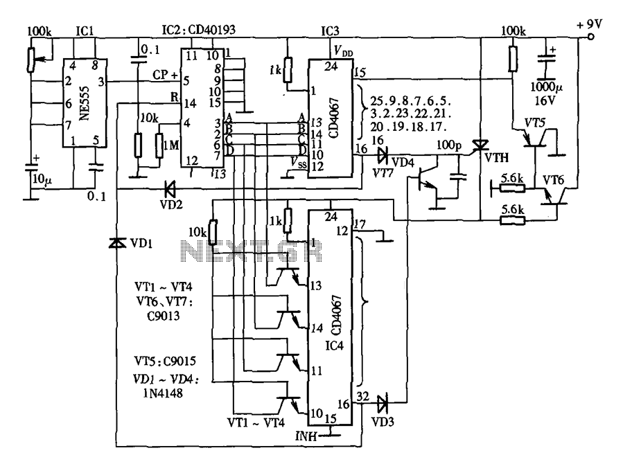
The lantern control circuit allows for the management of 30 outputs through an external driver circuit, specifically designed for water sports or large decorative lantern applications. The circuit features a control pulse generator, which regulates the lights, and an...

This circuit combines two or more audio channels into a single channel (for example, converting stereo to mono). It is capable of mixing multiple channels while consuming minimal power. The schematic illustrates two inputs, but additional inputs can be...
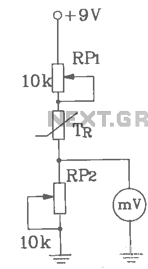
T-121 temperature sensor electronic thermometer circuit diagram shown below The T-121 temperature sensor circuit is designed to measure and display temperature readings accurately. The circuit typically consists of a temperature sensor, such as the T-121, which converts temperature variations into...
In all instances where Darlington transistors serve as output devices, it is crucial for the sensing transistor (Q4) to maintain close thermal contact with the output transistors. Consequently, a TO126-case transistor type was selected for ease of mounting onto...
This DC drill speed controller circuit allows for the adjustment of the rotational speed of a drilling machine. A mini-drill machine is always... This circuit utilizes a pulse-width modulation (PWM) technique to control the speed of a DC motor, which...
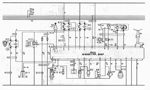
The following document contains information related to the electrical installation schematic diagram for the Volvo 440. It includes the wiring schematic for the Volvo 440, 460, and 480 series. The Volvo 440, 460, and 480 series vehicles feature a comprehensive...