
Fm Modulator Circuit

The FM modulator circuit utilizes the Motorola MC1648P as the core oscillator component, which is known for its stability and performance in frequency modulation applications. The inclusion of two Motorola MV-209 varactors allows for effective modulation of the oscillator frequency. These varactors are semiconductor devices that exhibit a variable capacitance based on the applied reverse voltage, making them ideal for frequency modulation tasks.
The 5000-ohm potentiometer serves a crucial role in adjusting the bias voltage applied to the varactors. This adjustment is essential for achieving the best linearity in the modulation process, impacting the fidelity and quality of the transmitted signal. The output frequency of the modulator is centered around 100 MHz, a common frequency for FM transmission, and can be fine-tuned by changing the inductance value in the circuit. The design allows for a frequency deviation of up to 10 MHz in either direction, providing flexibility in tuning the desired output frequency.
The output power level of the modulator is specified at -5 dBm, indicating the strength of the signal being transmitted. This power level is a critical parameter in ensuring that the signal can be effectively received by FM receivers without excessive noise or distortion. The prototype's varactor bias of 7.5 V was determined to provide optimal performance; however, it is important to note that varying the bias voltage may be necessary when different varactors are employed, as their characteristics can differ significantly.
In summary, this FM modulator circuit is designed for efficient frequency modulation using a well-defined oscillator and varactor configuration, with adjustable parameters to optimize performance for various applications. The FM modulator is built with a Motorola MC1648P oscillator. Two varactors, Motorola MV-209, are used to frequency modulate the oscillator. The 5000- potentiometer is used to bias the varactors for best linearity. The output frequency of approximately 100 MHz can be adjusted by changing the value of the inductor. The output frequency can vary as much as 10 MHz on each side. The output level of the modulator is -5 dBm. In this prototype, the varactor bias was 7.5 V for best linearity; but this could be different with other varactors.
Related Circuits
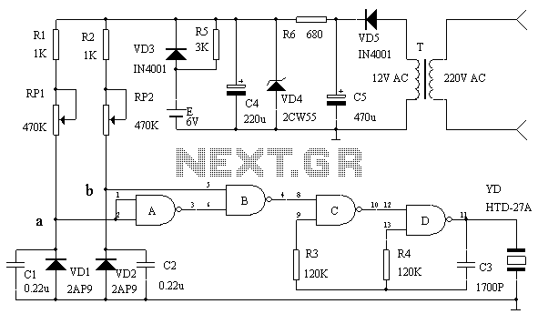
This circuit serves as an over-temperature alarm and cooling system utilizing CD4011 four NAND gate integrated circuits to monitor the oven's temperature. In the event of a thermostat circuit failure or power outage, if the internal temperature exceeds or...
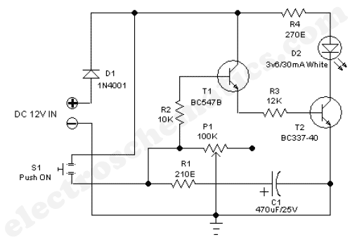
The 555 adjustable timer circuit initiates timing upon activation. A green LED illuminates to indicate that the timing process is underway. Once the designated time period concludes, the... The 555 timer IC is a versatile device widely used in various...
A circuit diagram for an animal repeller is provided. The circuit has been developed but is not functioning as intended. Assistance is requested for troubleshooting. The animal repeller circuit typically employs ultrasonic sound waves to deter animals from specific areas....

This design circuit project involves a clear glass sensor circuit intended for experimental or hobbyist applications. The concept is straightforward and relies on a homemade sensor unit that includes one high-efficiency ultra-bright red LED (D1) and a standard phototransistor. The...

The circuit is a battery charging system powered by Q2, Q6, R8, and D10, which provides constant current to charge the battery. When an external power supply is present, the charging current flows through R8 and D10 to charge...
As the position of the sun changes, the illumination level on the light-dependent resistors (LDRs) also varies, causing the input voltage for the window comparator to deviate from half of the supply voltage. Consequently, the output of the comparator...