
Clear Glass Sensor Circuit

The clear glass sensor circuit operates on the principle of light detection and reflection. The ultra-bright red LED (D1) emits light, which is directed towards the glass surface. When an object approaches the sensor, the light emitted by the LED reflects off the glass and returns to the sensor unit. The phototransistor, which is sensitive to the wavelength of the emitted light, detects this reflected light.
In the schematic, the LED (D1) is connected in series with a current-limiting resistor to ensure that it operates within its specified current ratings. This resistor prevents excessive current from flowing through the LED, which could lead to overheating and failure. The phototransistor is connected in a configuration that allows it to act as a switch. When the reflected light reaches a certain intensity, the phototransistor turns on, allowing current to flow through its collector-emitter path.
The output from the phototransistor can be further processed or used to trigger other components in a circuit. For example, it could activate a relay to turn on a light or sound an alarm when an object is detected near the glass. Additional components, such as capacitors and diodes, may be included in the circuit to filter noise and protect against voltage spikes.
This clear glass sensor circuit is particularly useful in applications such as automatic doors, security systems, or interactive displays where proximity detection is required. The simplicity of the design makes it an excellent choice for educational purposes, allowing hobbyists to learn about basic electronic principles while experimenting with sensor technology.This is a design circuit project for a clear glass sensor circuit can be used for experiment/hobby purposes. The concept is very simple and is based on a home-made sensor unit comprising one high efficiency ultra bright red LED (D1) and a standard ph ..
🔗 External reference
Related Circuits

A UJT organ circuit with a circuit diagram is explained in detail. A 2N4891 UJT is used for the operation of the circuit. The UJT (Uni-Junction Transistor) organ circuit is designed to utilize the unique characteristics of the 2N4891 UJT...
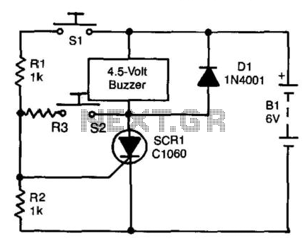
A self-interrupting device connected to a voltage source operates as a switch that continuously opens and closes; thus, the circuit does not latch in the conventional manner, allowing the alarm to function only while switch SI is closed. Due...

This circuit operates effectively across a broad frequency spectrum. XTAL 1 serves as a fundamental-frequency crystal. Tl and CI are adjusted to match the input frequency. This circuit can be utilized as a straightforward shortwave converter for AM radios,...

This circuit is designed for an LM1893 power line modem, which facilitates information transfer between remote locations using the power mains. The LM1893 serves as a power line interface for half-duplex (bi-directional) communication of serial bit streams employing various...

Current leakage protection is the most commonly used and effective leakage protection device. Current leakage protectors can be divided into electromagnetic and electronic types. The zero-sequence current transformer serves as the detection element, while electromagnetic leakage protection uses a...

The goal is to utilize a PC to measure the outdoor temperature using a serial-connected device equipped with a probe that can be conveniently placed outside. Although various options were found through online searches, many appear to be overly...