
FM Radio Receiver Circuit

This circuit is designed to receive FM radio signals, utilizing a regenerative RF stage for signal amplification and selection. The regenerative stage, implemented with transistor TR1, enhances the sensitivity and selectivity of the receiver. The circuit operates by feeding a portion of the output signal back to the input, which increases the gain and enables the reception of weaker signals.
Following the RF stage, the audio signal is processed through a multi-stage audio amplifier. The configuration can be either a two-stage or three-stage amplifier, utilizing transistors TR2, TR3, and TR4. Each stage is responsible for further amplifying the audio signal derived from the RF stage, ensuring that the output is suitable for driving speakers or headphones.
The circuit may include passive components such as resistors and capacitors, which are essential for biasing the transistors, filtering, and coupling between stages. The design also typically incorporates an antenna input for capturing the FM signals and may feature a tuning mechanism to adjust the circuit for different frequencies.
Overall, this FM radio receiver circuit is a straightforward yet effective design for amateur radio enthusiasts and serves as an excellent educational project for understanding the principles of radio frequency and audio amplification.This simple fm radio receiver circuit consists of a regenerative rf stage, TR1, followed by a two of three-stage audio amplifier, TR2 to TR4. In some areas.. 🔗 External reference
Related Circuits
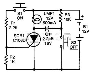
After the SCR is activated, capacitor CI charges up to nearly the full supply voltage through resistor R3 and the anode of the SCR. When switch S2 is later closed, it grounds the positive terminal of CI, causing the...
This circuit is designed for the selection of alternative sources. It integrates mechanical selection through a rotating switch S1, electronic control of relays RL1 to RL10, and optical indication of the selection via the display DSP1. The circuit operates by...
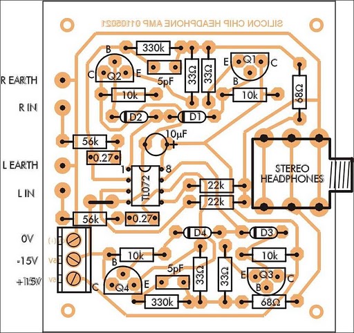
In addition to its primary function as a headphone amplifier, this circuit can be utilized for various applications requiring a wide bandwidth low-power amplifier. It is designed around an operational amplifier (op-amp), with its output current enhanced by a...

Power Amplifier Speaker Protection Circuit Schematic. When a power amplifier is switched on, a loud thump sound is often heard due to a sudden heavy discharge. The power amplifier speaker protection circuit is designed to prevent loud thump sounds during...
This circuit is designed for dimming devices powered by transformer-based power supplies, specifically those operating at 12, 24, or 48 volts, rather than standard 120 volts. The project involves various components, including a soldering iron, wire strippers, breadboard or...
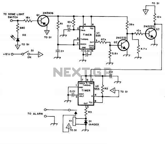
When this car alarm circuit is activated, it remains active for 80 seconds. There is a 15-second delay for the driver to enter and deactivate the alarm. All timings can be easily modified. The circuit utilizes two NE555 timers,...