
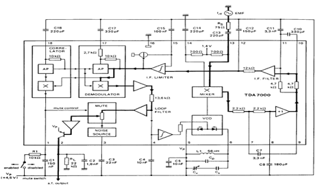
FM reciever with classic TDA7000

Parts: R1=47K, R2=22K, R3=100K, R4=39K, R5=10, R6-r12=7,5K - Optionally, R13-r21=15K - Optionally, P1=10K Logarithmic potentiometer, P2=100K Linear potentiometer, C1=39pF Ceramic, C2=47pF Ceramic, C3=2,2nF Polyester, C4, c14=220nF Polyester, C5=22nF Polyester, C6=10nF Polyester, C7, c18=180pF Ceramic, C8=150pF Ceramic, C9=100nF Polyester, C10, c13=330pF Ceramic, C11=220pF Ceramic, C12, c16=3300pF Ceramic, C15, c17=1800pF Ceramic, C19, c21, c22=10mF/16V electrolytic, C20=10nF Polyester, C23=47nF Polyester, C24, c25=470mF/16V electrolytic, L1, l2=5 Coils linked with internal diameter 4mm from cupreous isolated wire 0,6mm., IC1=TDA7000 with base DIL18, IC2=LM7805, IC3=LM386 with base DIL 8, D1=BB329 or BB105 or other than old tuner televisions., SPEAKER=Loudspeaker 8W/1W., S1=Switch of catering., AERIAL=50cm isolated wire, CONNECTOR DB25=Fastener of 25 pin parallel door PC (LPT) -Optional.
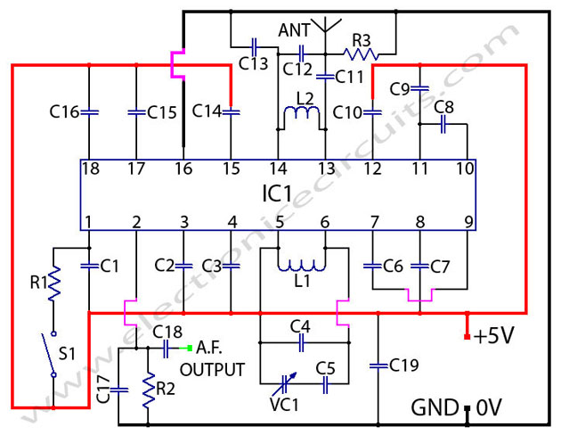
The circuit described is a radio receiver that offers adjustable sound intensity and frequency reception capabilities. The component P1, a 10K logarithmic potentiometer, is utilized to regulate the audio output level, while P2, a 100K linear potentiometer, adjusts the frequency reception. The design allows for optional interfacing with a personal computer (PC) to monitor the frequency output through a parallel port (DB25 connector).
The core of the circuit employs the TDA7000 integrated circuit (IC1), which is specifically designed for FM radio applications, supporting frequencies within the 88-108 MHz range. The circuit operates with a stabilized power supply voltage (Vcc) ranging from 9V to 12V and consumes approximately 100mA of current, making it suitable for battery-operated or portable applications.
The frequency modulation is enhanced through the use of a varicap diode (D1), which allows for electronic tuning by varying the capacitance in response to the control signals sent from the PC. The circuit includes various passive components such as resistors (R1 to R21) and capacitors (C1 to C25), which are carefully selected to ensure proper filtering, stability, and performance of the receiver.
The output audio is amplified by the LM386 (IC3), which is a low-voltage audio amplifier, providing sufficient power for driving an 8W loudspeaker. The LM7805 (IC2) serves as a voltage regulator, ensuring that the circuit receives a consistent 5V supply for the logic components.
Coils L1 and L2 are constructed from copper wire and are critical for tuning and signal reception, while the aerial, a simple 50 cm length of isolated wire, acts as the receiving antenna. The optional resistors R6 to R12 and R13 to R21 can be included to fine-tune the circuit's performance based on specific requirements or conditions.
Overall, this circuit design provides a comprehensive solution for a basic FM radio receiver with adjustable sound and frequency control, along with the potential for advanced interfacing with computer systems for enhanced functionality.With the P1 we regulate the intensity of sound. With the P2 we regulate the frequency of reception. Optionally: If you want to check the frequency with your PC it will be supposed you make the following energies: You assemble and the circuit that is in the blue frame. You cut the driver dj'pla in point A, as it appears in the circuit and you connect points A,V. If you know some language of programming as C ++, PASCAL, VISUAL BASIC, DELPHI etc you can write a program which will send in the parallel door (378 I) of PC a number from 0 until 255 checking thus the tendency of expense of simple D/A of converter (that it is in blue frame) and consequently and frequency of radio via passage VARICAP.
(As long as grows the number that sends in the parallel door, so much minimizes the frequency that receives the radio.) Stabilised tendency of catering: Vcc=9~12V. Frequency of reception: 88~108MHz. Consumption: 100mA. Parts: R1=47K, R2=22K, R3=100K, R4=39K, R5=10, R6-r12=7,5K - Optionally, R13-r21=15K - Optionally, P1=10K Logarithmic potentiometer, P2=100K Linear potentiometer, C1=39pF Ceramic, C2=47pF Ceramic, C3=2,2nF Polyester, C4, c14=220nF Polyester, C5=22nF Polyester, C6=10nF Polyester, C7, c18=180pF Ceramic, C8=150pF Ceramic, C9=100nF Polyester, C10, c13=330pF Ceramic, C11=220pF Ceramic, C12, c16=3300pF Ceramic, C15, c17=1800pF Ceramic, C19, c21, c22=10mF/16V electrolytic, C20=10nF Polyester, C23=47nF Polyester, C24, c25=470mF/16V electrolytic, L1, l2=5 Coils linked with internal diameter 4mm from cupreous isolated wire 0,6mm., IC1=TDA7000 with base DIL18, IC2=LM7805, IC3=LM386 with base DIL 8, D1=BB329 or BB105 or other than old tuner televisions., SPEAKER=Loudspeaker 8W/1W., S1=Switch of catering., AERIAL=50cm isolated wire, CONNECTOR DB25=Fastener of 25 pin parallel door PC (LPT) -Optional.
🔗 External reference
Related Circuits
This radio receiver can operate with any of the following transistors: ZN414, MK484, or TA7642. The radio receiver circuit is designed to utilize a variety of transistors, specifically the ZN414, MK484, and TA7642, which are commonly used in low-power AM...

TDA7000 FM Radio Receiver Circuit Using Tuning Capacitor GENERAL DESCRIPTION The TDA7000 is a monolithic integrated circuit for mono FM. The TDA7000 is designed as a complete FM radio receiver circuit, integrating all necessary functions for receiving mono FM signals....
The TDA7000 is an integrated circuit (IC) designed for FM portable radios, featuring a Frequency-Locked Loop (FLL) system with an intermediate frequency of 70 kHz. It incorporates several functions, including an RF input stage, mixer, local oscillator, IF demodulator,...
This 1 channel infrared transmitter/receiver remote control is the cheapest and simplest you can find. The transmitter transmits a sequence of pulses on 36 KHz frequency carrier. The diodes are Schottky type because of their low voltage drop (only...
The basic MK484 (Replacement for the ZN414) connected in its minimum configuration as a radio receiver for the A.M. Broadcast band and the upper half of the United States' FCC Part 15 Lowfer (1600-1750 meter) band. It's a circuit...
The TDA7000 is a monolithic integrated circuit designed for mono FM portable radios or receivers, emphasizing minimal peripheral components for compact size and cost-effectiveness. This integrated circuit features a Frequency-Locked-Loop (FLL) system with an intermediate frequency of 70 kHz....