
FM reciever with MC13136

Now, a tiny signal at 455 kHz will vary slightly around 455 kHz depending on the FM modulation (+/- some kilohertz). This tiny signal must be amplified to a level where the audio signal can be demodulated from the RF signal. The tiny RF signal will also vary in strength depending on proximity to the transmitter. A constant level that is not dependent on the distance to the transmitter is desired.
An amplifying-limiting stage is present at pins 9, 10, 11, and 12. This stage amplifies the tiny RF signal to a constant safe level where the demodulator can extract the audio signal. This stage may be referred to as a voltage-controlled gain stage. As the signal strength varies with distance from the transmitter, the limiter adjusts the gain accordingly. The amplifier has a wide gain range, from 100 to several million times. The voltage controlling the gain is known as the Received Signal Strength Indicator (RSSI) and can be found at pins 12 and 15. The voltage ranges from 0.4 to 1.2 volts.
The lowest level of 0.4 V corresponds to an RF voltage of 0.22 µV, while the highest level of 1.2 V corresponds to an RF voltage of 2.3 mV (very high). The RSSI output signal is used to control the audio amplifier's operation. When the RSSI is low, indicating a weak or nonexistent signal, the speaker should be turned off to avoid noise. Conversely, when the RSSI level rises, indicating a probable RF signal, the audio speaker should be activated to allow sound output. The RSSI signal can also be connected to an analog voltmeter to display signal strength.
At pins 13 and 14, a ceramic filter or "quad coil" is connected, which extracts the sound from the 455 kHz IF signal. Further details on this component can be found on quad coil resources. At pin 17, the recovered audio signal is amplified to 200 mV.
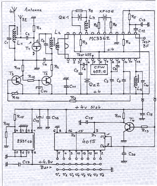
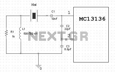
The MC13135/MC13136 circuit exemplifies advanced FM communication receiver design, incorporating dual conversion for improved selectivity and sensitivity. The integration of RSSI for automatic gain control enhances usability in varying signal conditions, making it suitable for diverse applications in communication systems. The design facilitates efficient demodulation of audio signals while maintaining a robust output across fluctuating input conditions.One of the circuit I use in my projects is the MC13135/MC13136. It is the second generation of single chip, dual conversion FM communication receivers developed by Motorola. Major improvment in signal handling, RSSI and first oscillator operation have been made. At pin 22 you will find the RF-input this is the antenna input connection. This receiver will receive at 49.7 MHz. The RF signal will mix with the crystal oscillator (39MHz) pin 1 and 2. The product frequency 49.7-39 =10.7MHz will come out at pin 20. A ceramic filter removes all other frequences except the 10.7MHz wich will enter at pin 18. Here you will find a new mixer wich will mix the 10.7MHz with another crystall oscillator (10.245MHz) pin 5 and 6.
The product frequence 10.7-10.245 =455kHz will come out at pin 7. A ceramic filter removes all other frequences except the 455kHz wich will enter pin 9. Now, you have tiny signal at 455kHz wich will vary a little around 455kHz depending on the FM-modulation (+/- some kiloherts). This tiny signal must be amplified to a level where the audiosignal can be demodulated from the RF-signal.
The tiny RF-signal will also vary in strength depending how close you are to the transmitter. What you want is a constant level wich is not depending on the distance to the transmitter. So, there is a amplifying-limiting stage at pin 9,10,11, and 12. This stage amplify the tiny RF-singal to a constant safe level where the demodulator can demodulate the audio-signal. This stage could be called a voltage controlled gain-stage. As you might understand, the closer you are to a transmitter the strong the RF-signal will be, and in such case the limiter will not have to gain the signal so much.
The amplifier has a very wide amplifying area, from 100 to some milion times. The voltage to control the gain is called (Received Signal Strength Indicator) RSSI and can be found at pin 12 and 15. Here you will find a voltage from 0.4 - 1.2 volt. Lowest level is 0.4 V means that the RF-voltage is 0.22uV and Highest level is 1.2 V means that the RF-voltage is 2.3mV (very high) .
The RSSI output signal is used to turn the audio amplifier on/off. When the RSSI is low you have a very weak signal or maybe no signal at all, and you don't want to hear the noise, so the speaker should be turned off. When the RSSI level rise you will probably have a RF-signal and the AF-speaker should be turned on to let you hear the sound.
The RSSI signal can also be connected to a analogue voltmeter to display the Signal Strength. I will continue to explain the receiver. At pin 13 and 14 is a ceramic filter or a "quad coil" connected. This componet will bring out the sound from the 455KHz IF-signal. If you want to learn more about this look at my quad coil page. At pin 17 the recovered audio-signal is amplifier to 200mV. 🔗 External reference
Related Circuits
This circuit generates audio musical notes that can be heard from a distance of up to 10 meters. It consists of two main components: an infrared (IR) music transmitter and an IR music receiver. The IR music transmitter operates...
The diagram of detail of Fig.2 gives additional precise details: The signal HF collected by the antenna is amplified by T1, framed reel S of agreement L1 and L2. To vary the profit of T1, it is enough to...
Complete Dual Conversion FM Receiver. Input frequency range 0-200MHz. Voltage buffered RSSI with 70 dB of usable range. Low voltage operation 2-6 VDC. VHF Colpitts First LO for Crystal or VCO operation. Isolated Tuning diode. Buffered first LO output...
This 1 channel infrared transmitter/receiver remote control is the cheapest and simplest you can find. The transmitter transmits a sequence of pulses on 36 KHz frequency carrier. The diodes are Schottky type because of their low voltage drop (only...
Tesla's free-energy receiver was patented in 1901 as An Apparatus for the Utilization of Radiant Energy. The patent refers to "the Sun, as well as other sources of radiant energy, like cosmic rays." That the device works at night...
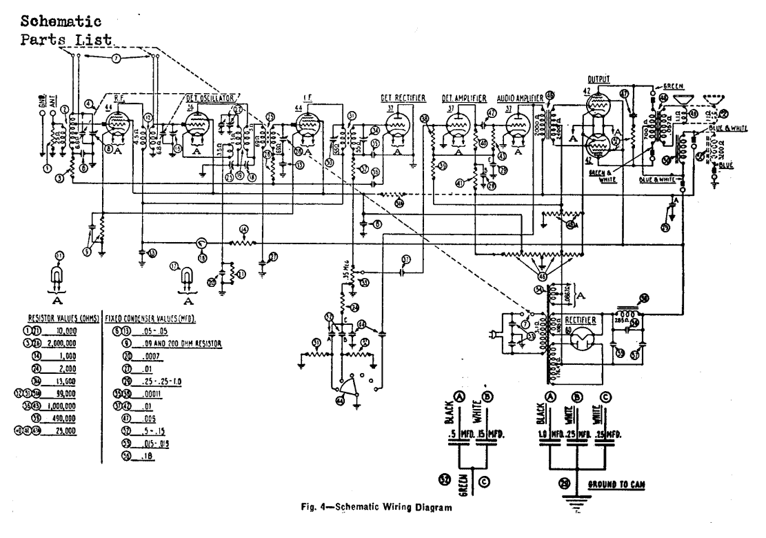
The Philco radio is a nine tube superheterodyne receiver combining standard broadcast, police and airplane reception and employs the high efficiency 6.3 volt filament tubes, automatic volume control, bass compensating tone control, shadow tuning and push pull pentode output. The...