
FM Transmitter (2N2222)
")
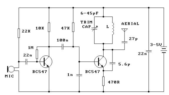
This circuit design employs two 2N2222 transistors, which serve as the core components for amplification and oscillation. The first transistor, Q1, is configured as a common emitter amplifier, receiving audio input from a microphone. The amplified audio signal is then fed into the base of the second transistor, Q2, which is part of the oscillator circuit.
The oscillator circuit, comprising Q2, capacitor C5, and inductor L1, is designed to operate within the frequency range of 80 to 130 MHz. This range is suitable for FM transmission and complies with FCC regulations for unlicensed devices. The oscillator is voltage-controlled; thus, the frequency can be modulated by varying the amplitude of the audio signal applied to Q2's base. This modulation allows for the transmission of audio signals over radio frequencies.
Resistor R6 plays a crucial role in this circuit by limiting the input to the RF section. The value of R6 can be adjusted to control the volume of the audio input, ensuring that the transmitter operates effectively without distortion. The tuning elements, L1 (inductor) and C6 (capacitor), can be custom-made to achieve the desired resonant frequency and stability of the oscillator. The design allows for flexibility in tuning, which is essential for optimizing performance based on the specific application and environment.
Overall, this simple FM transmitter circuit provides an effective means of wireless audio transmission while adhering to regulatory standards. The use of commonly available components like the 2N2222 transistors makes it accessible for hobbyists and engineers alike.This circuit is a simple two transistor (2N2222) FM transmitter. No license is required for this transmitter according to FCC regulations regarding wireless microphones. If powered by a 9 volt battery and used with an antenna no longer than 12 inches, the transmitter will be within the FCC limits.
The microphone is amplified by Q1. Q2, C5, and L1 form an oscillator that operates in the 80 to 130 MHz range. The oscillator is voltage controlled, so it is modulated by the audio signal that is applied to the base of Q2. R6 limits the input to the RF section, and it's value can be adjusted as necessary to limit the volume of the input.
L1 and C6 can be made with 🔗 External reference
Related Circuits

This circuit is designed for low power operation and can be tuned to function within the frequency range of 87-108 MHz, achieving a transmission distance of 20 to 30 meters. The circuit utilizes a pair of BC548 transistors, which,...

This compact FM transmitter operates with an RF output power of 500mW and can be powered by a 12-15V battery or power supply. The signal is modulated using frequency modulation (FM) techniques and employs four transistors. The transmitter consists...
This FM transmitter circuit is very simple and has acceptable transmission. The signal transmitted from this FM transmitter circuit can be received at almost 300 meters in open air. The circuit requires a 3-volt operating voltage and can be...
FM transmitter IC manufacturers and suppliers include FM transmitter IC manufacturers with Bluetooth capabilities. The FM transmitter features an integrated circuit with four channels. The TNA029 IR audio transmitter IC is a low-cost solution with high performance. The FM transmitter...
This schematic represents an FM transmitter capable of delivering an output power between 3 to 3.5 W, operating within the frequency range of 90 to 110 MHz. While the stability of the circuit is acceptable, the integration of a...
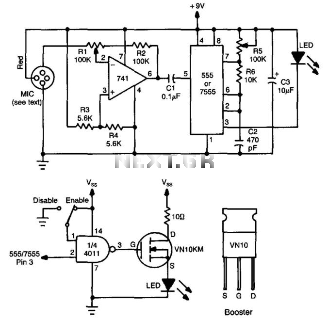
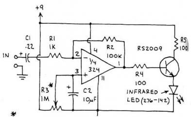
This circuit utilizes a 741 audio amplifier, which is connected to an amplified microphone, an FM modulator, and a CMOS timer functioning as a voltage-controlled oscillator (VCO). The timer output drives an LED, which is pulsed to produce an...