
FM transmitter circuit diagram

The Colpitts oscillator is a type of electronic oscillator that utilizes a combination of capacitors and an inductor to generate oscillations at a specific frequency. The frequency of oscillation is primarily influenced by the capacitance of the variable capacitor diode, which allows for fine-tuning of the output frequency. This is achieved by adjusting the biasing voltage applied to the diode through a 47K potentiometer, enabling the user to modify the center frequency effectively.
In practical applications, the oscillator can be connected to either a 75 cm telescopic antenna or a length of hook-up wire, providing flexibility in transmission options. Empirical testing has shown that even a 6 cm hook-up wire can yield satisfactory results, achieving a transmission range of approximately 100 meters when paired with a quality FM receiver.
The construction of the oscillator circuit is cost-effective, with an estimated expense of around Rs. 35. The inductor, which plays a crucial role in the oscillation process, can be fabricated directly onto a printed circuit board (PCB) as a track. This process involves transferring the required dimensions onto a copper board and subsequently etching it to create the inductor shape. In cases where maintaining a 1 mm spacing in the PCB design proves difficult, a sharp blade may be utilized to carefully remove any excess copper, ensuring the integrity of the circuit.
Alternatively, a copper wire can be employed to construct a square spiral inductor, adhering to the specified dimensions provided in the design. It is important to note that slight deviations from the recommended dimensions are permissible, allowing for practical adjustments during construction. Additionally, an alternative inductor design using 18 SWG copper wire can be explored, consisting of 5 turns with a diameter of 5 mm and an air core. The center tap for this inductor can be taken from either the 2nd or 3rd turn, providing further customization options for the circuit.
This oscillator design and its associated information are intended strictly for personal use. Users are advised that any commercial applications require explicit permission from the authors. The content provided is offered without warranties of any kind, and the authors disclaim any responsibility for errors or damages that may arise from the use of the information presented. It is also noted that the site may contain copyrighted material, which should not be reproduced without the necessary permissions.Colpitts oscillator. Its frequency depends on the capacitance of the vary cap diode. The center frequency is changed by varying the biasing voltage of the vary cap through the 47K pot. You can use a 75cm telescopic antenna or simply a length of hook-up wire. Mine worked fine with a 6cm hook-up wire and gave a range of 100m with a good FM receiver. The approx. cost of the circuit is around Rs. 35 The coil shown below can be constructed on the PCB itself as PCB track. Just transfer the dimensions on a copper board and etch it. If the 1mm spacing is difficult use a sharp blade to remove unwanted copper. You can also use a copper wire and construct a square spiral of the dimensions shown below. Please note that a small deviation from the given dimensions is permissible. Note: You can even try a coil made of 18SWG copper wire of 5 turns and 5mm dia with air core. The center tap can then be taken at the 2nd or 3rd turn. ( I have`nt tried it tell me if it works well) Disclaimer: All the information present on this site are for personal use only. No commercial use is permitted without the prior permission from authors of this website. All content on this site is provided as is and without any guarantee on any kind, implied or otherwise.
We cannot be held responsible for any errors, omissions, or damages arising out of use of information available on this web site. The content in this site may contain COPYRIGHTED information and should not be reproduced in any way without prior permission from the authors.
🔗 External reference
Related Circuits
The metal detector circuit comprises several key components, including a power circuit, a sine wave oscillator, a PLL (phase-locked loop) circuit, and a hybrid amplifying circuit. The power circuit is made up of batteries GBI and GB2, filter capacitors...
The NE5532 preamplifier is widely recognized for its excellent performance. It is now being utilized as a small power amplifier. While the general operational amplifier (op-amp) circuit remains similar, there are notable changes in some resistors and capacitors, leading...

This document describes the transmitter system supplied to Radio Glen for testing as designed and constructed by Henry. The transmitter is supplied in prototype form and has the physical limitations of an instrument constructed using prototyping techniques. The transmitter...
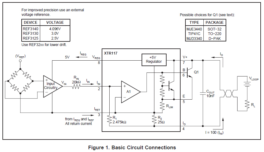
A simple circuit is required to simulate sensor inputs to a PLC. The sensors operate at 12VDC and output a current of 4-20mA. The XTR series devices are being considered for this application, but clarification is needed regarding which...

This design circuit is for a tone/frequency detector (decoder) that can detect the presence of a signal with a specific tone. The output of the circuit will be active if the signal matches the tone of an internal oscillator....
A purchase was made of the EDE702 along with an LED-backlit LCD character display. After acquiring the EDE702, it was determined that it lacked sufficient integration with HD44780-compatible displays to justify its cost. However, utilizing it was preferable to...